Oil-fired frac water heater

a frac water heater and oil-fired technology, which is applied in the field of oil-fired frac water heaters, can solve the problems of affecting the effectiveness of the construction of a permanent heating facility at the well site, poor heating suitability, and inconvenient use, so as to maximize the combustion efficiency, maximize the atomization and combustion of fuel oil, and maximize the combustion efficiency

Active Publication Date: 2013-09-17
CHANDLER RONALD L
View PDF76 Cites 69 Cited by
  • Summary
  • Abstract
  • Description
  • Claims
  • Application Information

AI Technical Summary

Benefits of technology

[0018]The present invention further includes a novel forced-air combustion and cooling system. The forced-air system is comprised of a primary air system and a secondary air system. The primary air system provides pressurized air directly to the oil-fired burner assemblies to maximize atomization and combustion of the fuel oil. The secondary air system provides pressurized air to strategic positions within the firebox to assist in controlling the cooling of the firebox and to maximize the combustion of the fuel / air mixture. The primary and secondary air systems are powered by hydraulic pumps integral to the overall system. The present invention also Includes systems for regulating and adjusting the fuel / air mixture within the firebox to maximize the combustion efficiency.
[0019]The improved system of the present invention also includes several subsystems for maximizing the safety and efficiency of the heat exchanger system. The system includes a novel hood mechanism attached to the exhaust stack of the firebox. In addition, the system includes a novel intake air muffler / silencer system, which significantly reduces the noise generated by the intake of such large quantities of ambient air.

Problems solved by technology

Consequently, the construction of a permanent heating facility at the well site is not cost effective.
While gas-fired heat sources are adequate for performing many oil field servicing tasks, they exhibit a number of inherent drawbacks.
These inherent limitations significantly impact their effectiveness in performing certain heating operations at remote oil field work sites.
For example, frac jobs typically require the production of massive volumes of heated water.
While gas-fired heat sources are certainly capable of heating fluids such as water, they are poorly suited to heating in a timely manner large volumes of continuously flowing water in many commonly occurring climactic and atmospheric conditions.
Moreover, the logistics involved in conducting such heating operations at remote work sites negatively impacts the cost efficiencies of such a system.
Thus, gas-fired heating units often lack sufficient heating capacity to produce sufficient quantities of heated water rapidly enough for the required operation to be completed.
Needless to say, the logistics involved with providing additional holding tanks at the remote work site and the additional costs incurred in overheating or reheating the supply water negatively impacts the efficiency of the overall operation.
While the technique of overheating and stockpiling supply water can ameliorate some the shortcomings in the heating capacity of gas-fired heat sources, in certain circumstances (e.g., severely cold weather or high altitude) it is inadequate.
First, the temperature change requirement for the system is simply greater in colder weather.
Thus, it takes longer for the gas-fired heating unit to preheat the supply water.
The problem is further compounded by the fact that the stockpiled preheated water cools more rapidly in colder weather.
In addition, propane gas requires large and heavy high-pressure fuel tanks for its transport to remote sites.
The size of such high-pressure fuel tanks is, of course, limited by the size of existing roads.
Furthermore, there are several safety concerns which must be taken into consideration when using gas-fired heat sources.
An open flame at the well site poses a substantial risk of explosion and uncontrolled tire, which can destroy the investment in the rig and injure or even cost the lives of the well operators.
Moreover, open flame burners are particularly susceptible to erratic burning or complete blow-out in gusty wind conditions.
While safety concerns are of overriding importance, compliance with the no open-flame regulations requires additional time and expense to conduct heated fluid well treatments.

Method used


Image

  • Oil-fired frac water heater
  • Oil-fired frac water heater
  • Oil-fired frac water heater

Examples


Embodiment Construction

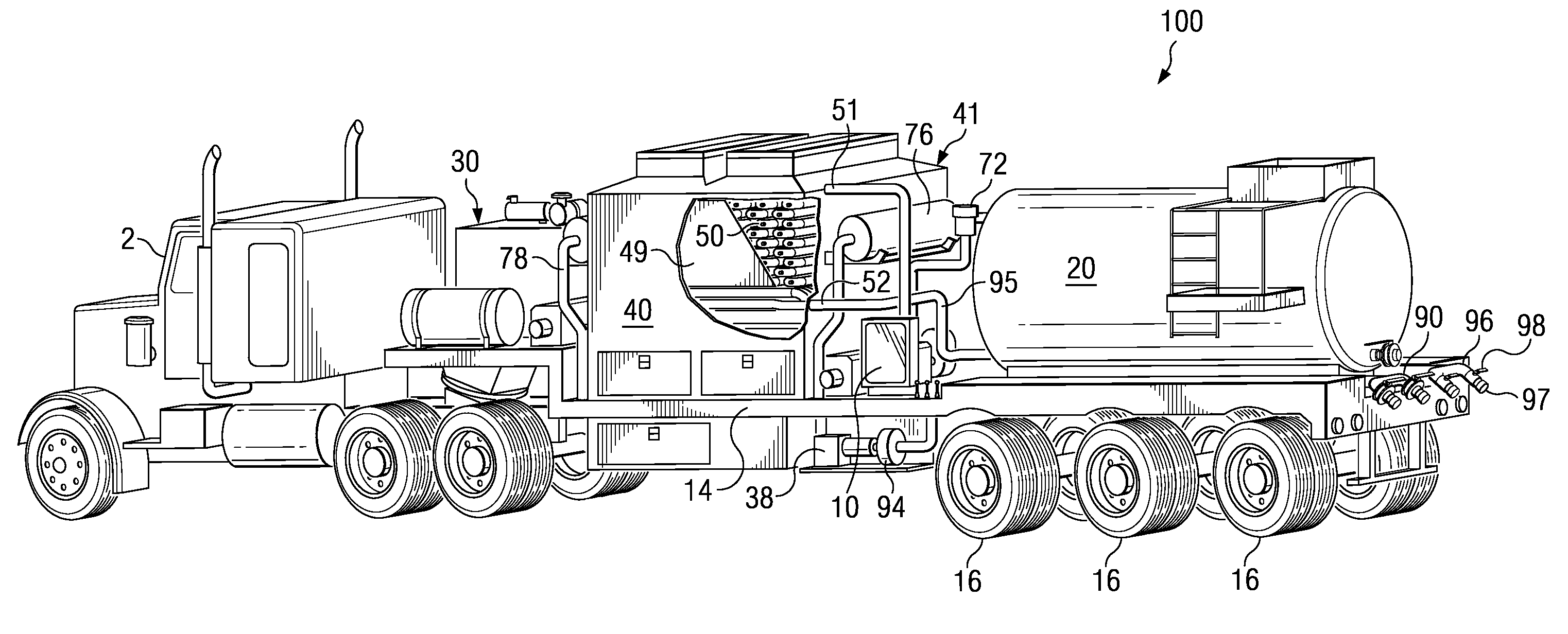
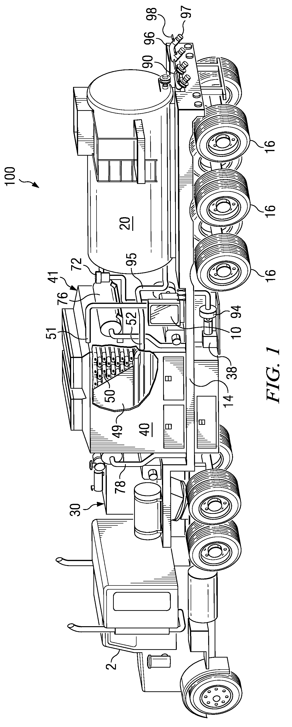
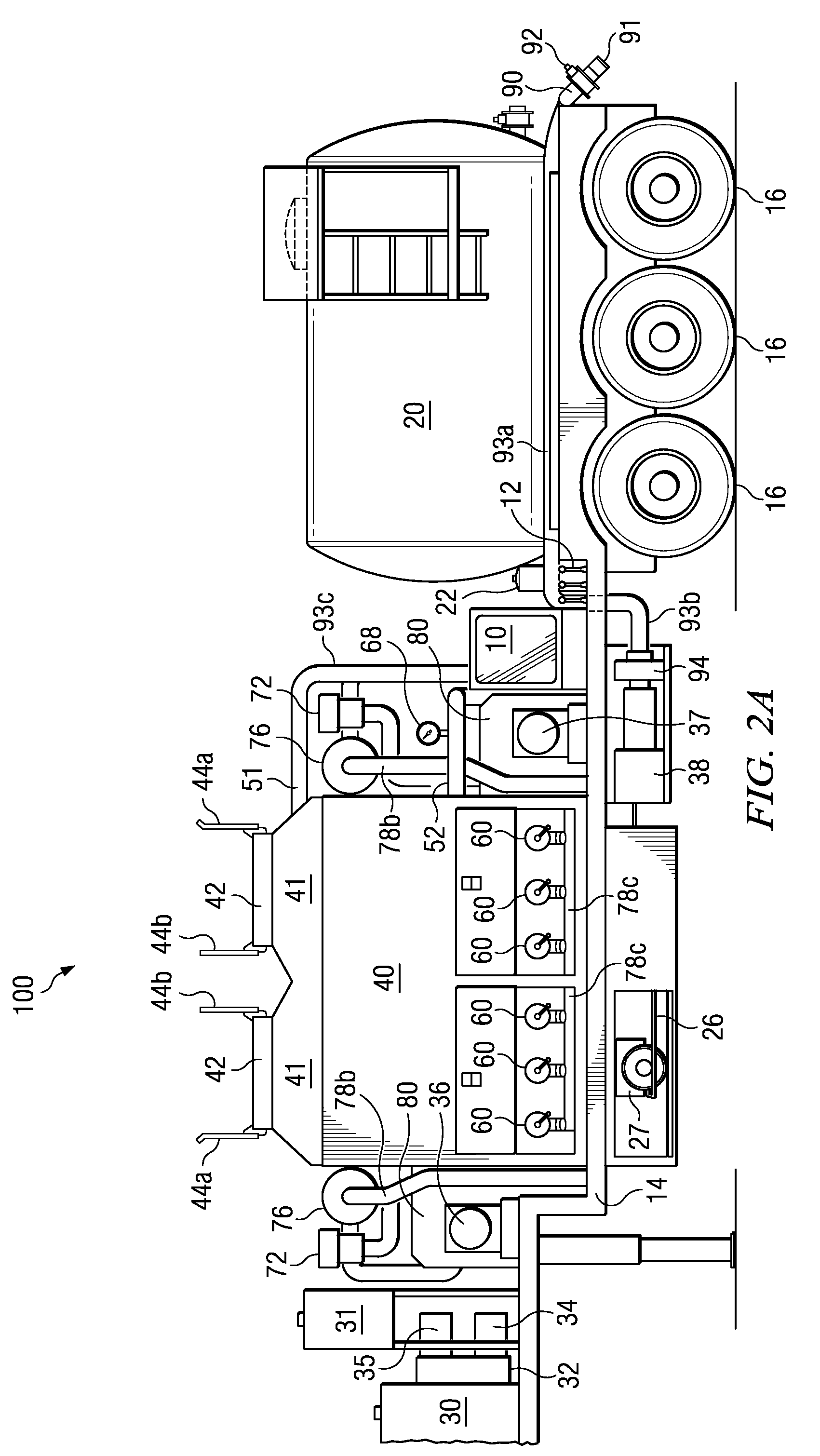
[0035]With reference to the Figures, and in particular to FIG. 1 powered and 2A-C, an embodiment of the improved oil-fired heat exchanger system 100 of the present invention is shown. The embodiment 100 shown in the Figures is configured to be an oil-fired frac water heater system. As depicted, the embodiment of the frac water heater system 100 is configured on a drop deck trailer 14 and suitable for transport to remote oil field sites. The system 100 includes a fuel storage and supply system, a firebox 40 containing a single heat exchanger 50, primary 70 and secondary 80 air supply systems connected to the firebox 40, and an auxiliary power plant 30 for driving an accessory gearbox 32. The accessory gearbox 32, in turn, drives multiple hydraulic pumps, which power a main fluid pump 94 and the air supply systems. The main fluid pump 94 is used to draw fluid, such as water, from a fluid source and supply it to the intake 51 of the heat exchanger 50. The hydraulic pressure generated b...


PUM


Abstract

The present invention overcomes many of the disadvantages of prior art mobile oil field heat exchange systems by providing an oil-fired heat exchange system. The present invention is a self-contained unit which is easily transported to remote locations. The present invention includes a single-pass tubular coil heat exchanger contained within a closed-bottom firebox having a forced-air combustion and cooling system. The rig also includes integral fuel tanks, hydraulic and pneumatic systems for operating the rig at remote operations in all weather environments. In a preferred embodiment, the oil-fired heat exchanger system is used to heat water on-the-fly (i.e., directly from the supply source to the well head) to complete hydraulic fracturing operations. The present invention also includes systems for regulating and adjusting the fuel / air mixture within the firebox to maximize the combustion efficiency. The system includes a novel hood opening mechanism attached to the exhaust stack of the firebox.

Description

CROSS-REFERENCE TO RELATED APPLICATION[0001]This application claims the benefit of and priority to a U.S. Provisional Patent Application No. 61 / 078,734 filed Jul. 7, 2008. the technical disclosure of which is hereby incorporated herein by reference.BACKGROUND OF THE INVENTION[0002]1. Technical Field[0003]The present invention relates to an apparatus and method for heating a water or petroleum based fluid for injection into an oil or gas well or into a pipeline system.[0004]2. Description of the Related Art[0005]It is common in the oil and gas industry to treat oil and gas wells and pipelines with heated fluids such as water and oil. For example, one such application commonly known as a hydraulic fracturing job or “frac” job, involves injecting large quantities of a heated aqueous solution into a subterranean formation to hydraulically fracture it. Such frac jobs are typically used to initiate production in low-permeability reservoirs and / or re-stimulate production in older producing...

Claims


Application Information

Patent Timeline
Patent Type & Authority Patents(United States)
IPC IPC(8): F24H3/06F28D15/00
CPCF24H1/06F24H1/40F24H9/2035E21B43/2405F24H1/009F24H1/08E21B43/26E21B43/267F28D7/0066F28D7/02F28D7/08E21B43/2607F24H15/31F24H15/219F24H15/174
Inventor CHANDLER, RONALD L.
Owner CHANDLER RONALD L
Why Eureka
Try Eureka