Oscillating positive respiratory pressure device
- Summary
- Abstract
- Description
- Claims
- Application Information
AI Technical Summary
Benefits of technology
Problems solved by technology
Method used
Image
Examples
first embodiment
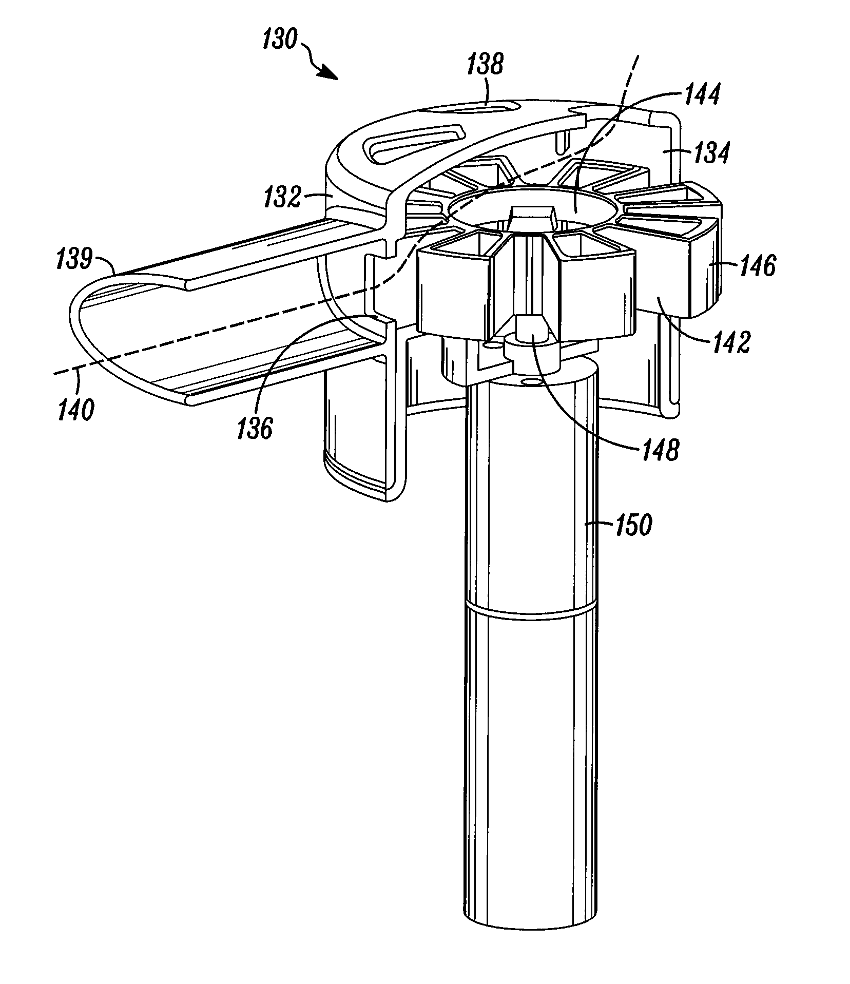
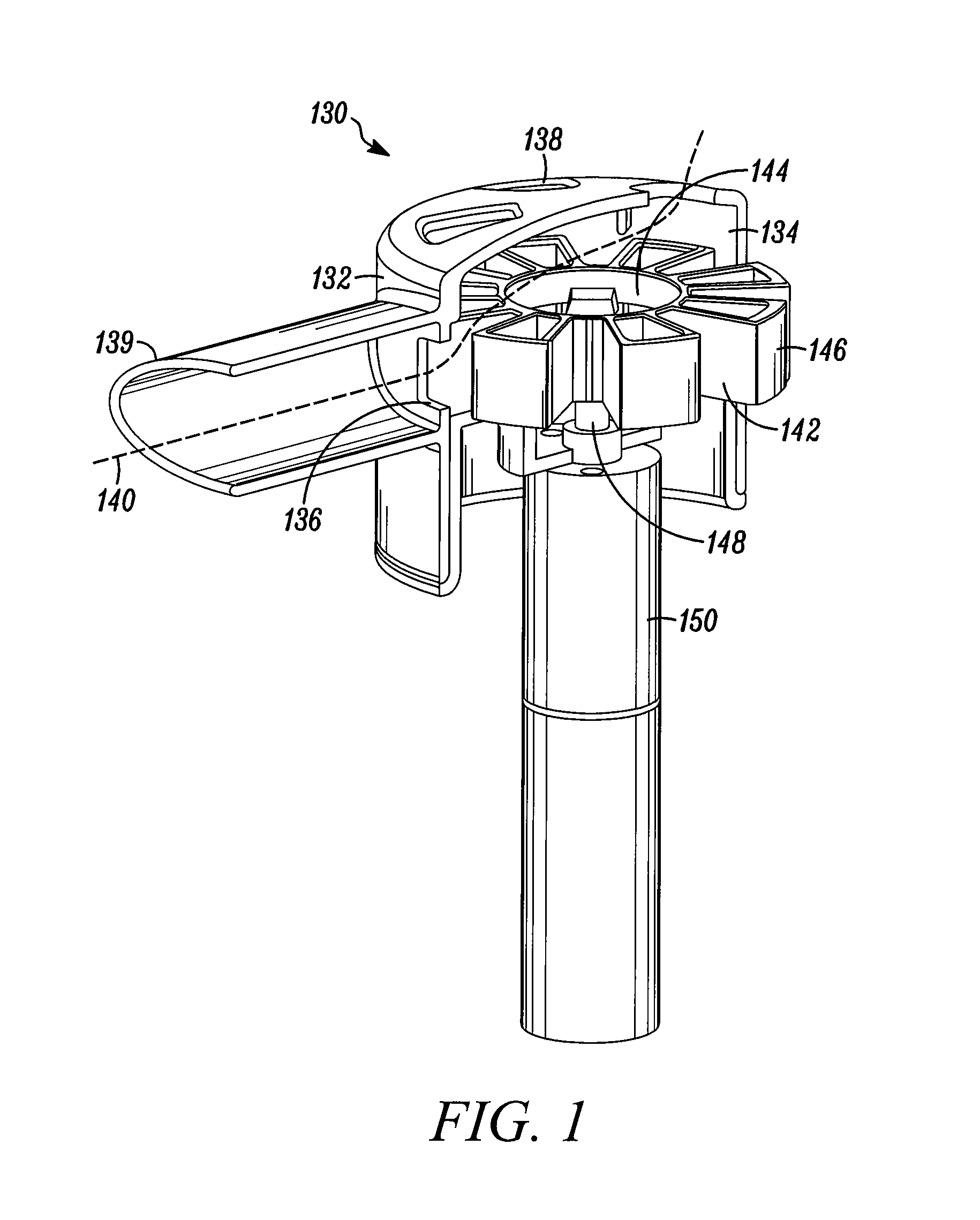
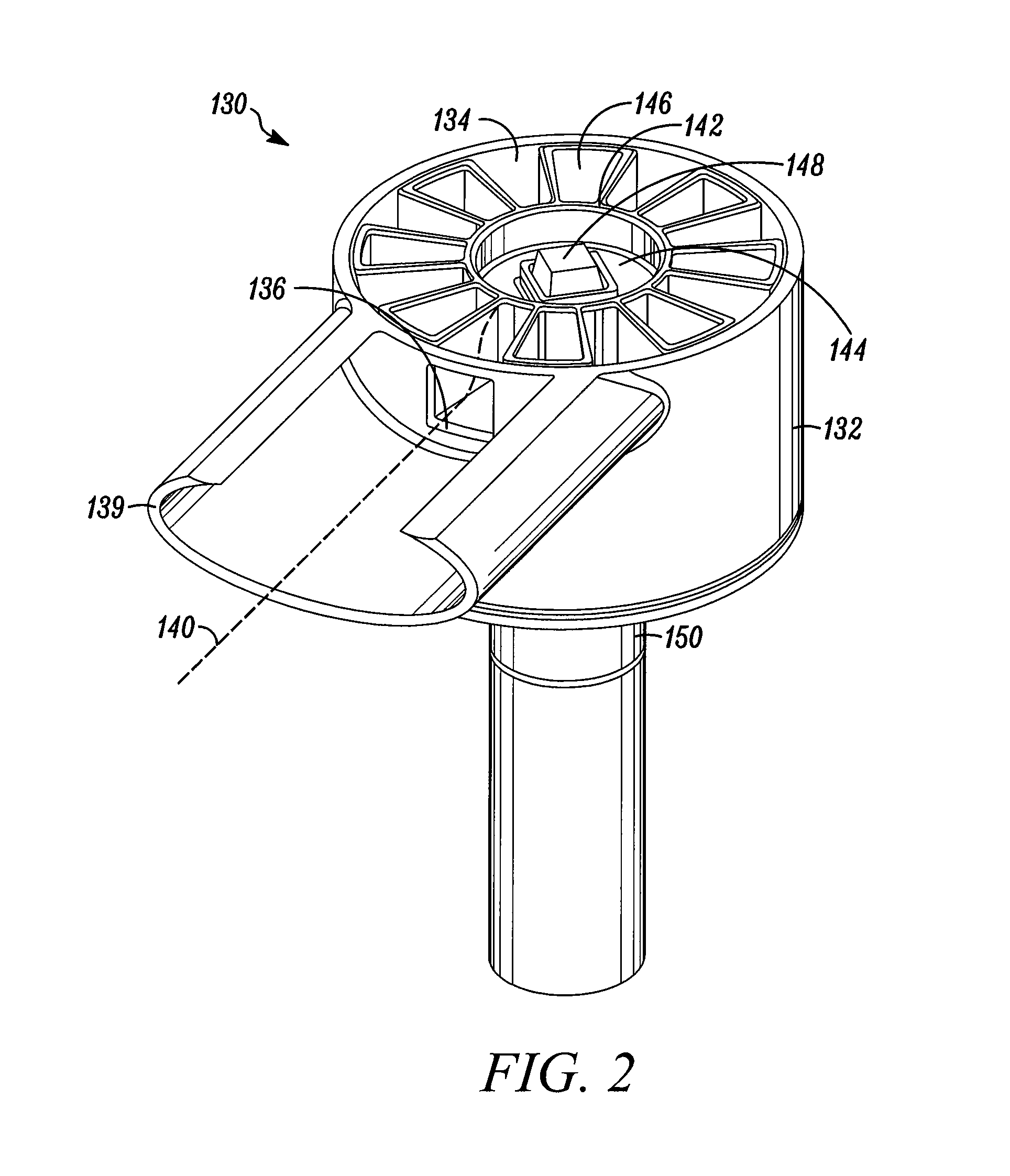
[0035]Referring to FIG. 1, an OPEP device 130 is shown with a side portion of a housing 132 removed for purposes of illustration. In general, the OPEP device 130 comprises a housing 132 having an interior chamber 134, a chamber inlet 136, and a chamber outlet 138. An exhalation flow path 140 is defined through chamber inlet 136, the interior chamber 134, and the chamber outlet 138. The housing 132 may also be associated with a mouthpiece 139 for receiving exhaled air. Although the mouthpiece 139 is shown in FIG. 1. as being fixedly attached to the housing 132, it is envisioned that the mouthpiece 139 may be removable and replaceable with a mouthpiece 139 of a different shape or size. Alternatively, other user interfaces, such as breathing tubes or gas masks (not shown) may be associated with the housing 132. Preferably, the housing 132 is openable so that the interior chamber 134 and the parts contained therein can be periodically accessed, cleaned, and replaced. The housing 132 may...
second embodiment
[0046]Referring to FIG. 6, an OPEP device 230 is shown with a side portion of a housing 232 removed for purposes of illustration. In general, the OPEP device 230 has a larger housing 232 for accommodating multiple restrictor members 242. The housing 232 also has an interior chamber 234, a chamber inlet 236, and a chamber outlet 238. A flow path 240 is defined through the chamber inlet 236, the interior chamber 234, and exiting the chamber outlet 238.
[0047]Within the interior chamber 234, the restrictor members 242 may either be stacked atop one another and operatively connected to a shaft 248, or, in the alternative, each individually connected to the shaft 248. Furthermore, each restrictor member 242 may have a different number of blocking segments 246. As in the prior embodiment, the housing 232 is openable so that a user may remove and replace the restrictor member 242 positioned adjacent the chamber inlet 236. Thus, the interior chamber 232 may conveniently store multiple restri...
third embodiment
[0049]Referring to FIGS. 7-8, an OPEP device 330 is shown. As shown in FIG. 7, the OPEP device 330 is adapted to connect to an output 360 of a nebulizer 352 for the simultaneous administration of OPEP and aerosol therapies. The OPEP device 330 generally includes a respiratory portal 354 for fluidly interconnecting the nebulizer 352, a mouthpiece 339, and the OPEP housing 332. The OPEP device 330 may be configured such that it can be used either in combination with the nebulizer 352 or solely for administration of OPEP therapy. FIG. 7 also illustrates a motor housing 356 for housing a motor (not shown) and batteries (not shown) for supplying power to the motor.
[0050]Referring to FIG. 8, a side view of the respiratory portal 354 is shown without the nebulizer 352 for delivery of OPEP therapy only. In FIG. 8, the chamber inlet 336 is located above the interior chamber 334 and the chamber outlet 338 is located directly beneath the mouthpiece 339. However, it should be noted that the cha...
PUM
 Abstract
Description
Claims
Application Information
 - R&D
- Intellectual Property
- Life Sciences
- Materials
- Tech Scout
- Unparalleled Data Quality
- Higher Quality Content
- 60% Fewer Hallucinations
Browse by: Latest US Patents, China's latest patents, Technical Efficacy Thesaurus, Application Domain, Technology Topic, Popular Technical Reports.
© 2025 PatSnap. All rights reserved.Legal|Privacy policy|Modern Slavery Act Transparency Statement|Sitemap|About US| Contact US: help@patsnap.com


