
Rock screen with particle trap

a technology of particle traps and rock screens, applied in the field of ink jet recording apparatus and methods, can solve problems such as print quality defects and print quality defects

Active Publication Date: 2013-10-01
XEROX CORP
View PDF4 Cites 2 Cited by
  • Summary
  • Abstract
  • Description
  • Claims
  • Application Information

AI Technical Summary

Benefits of technology

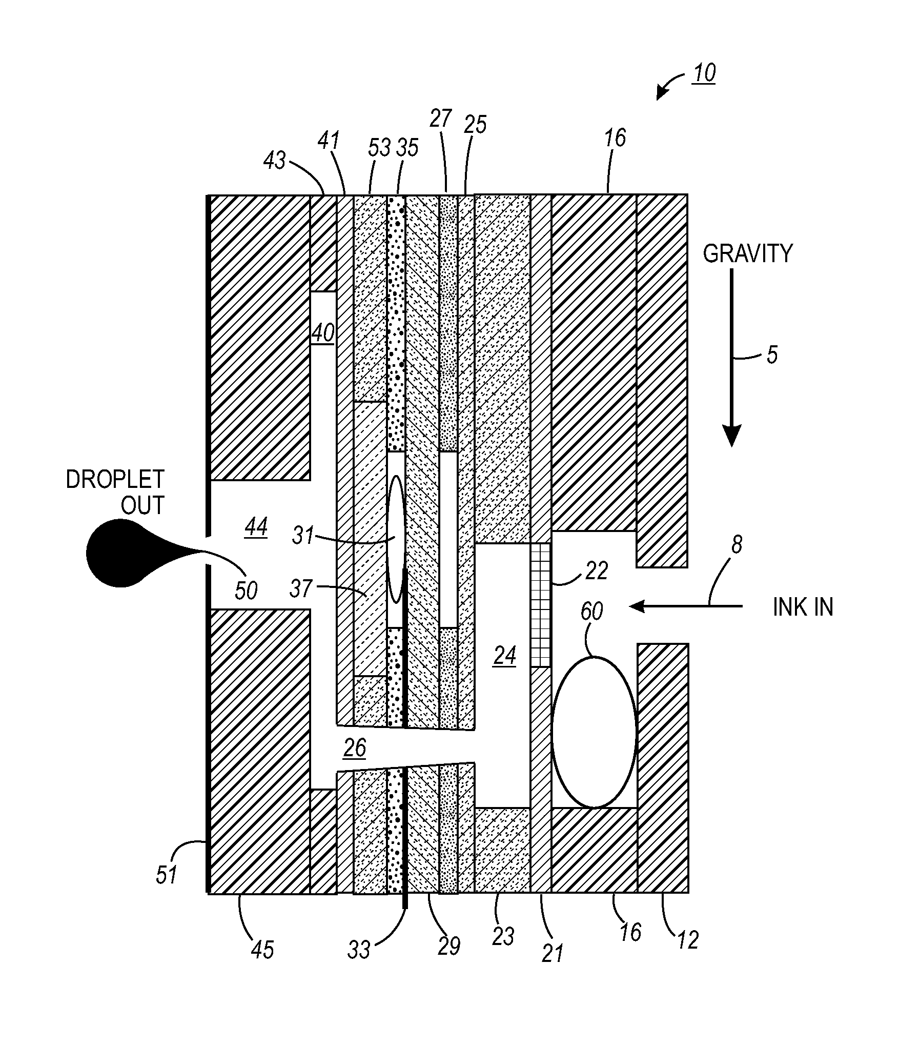
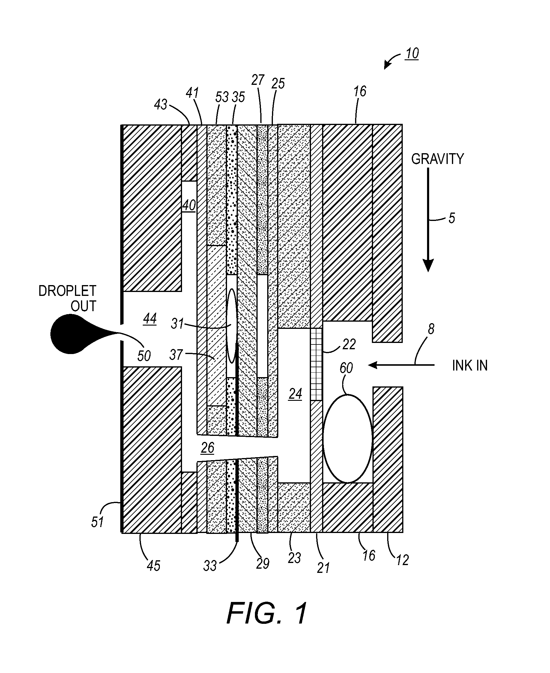
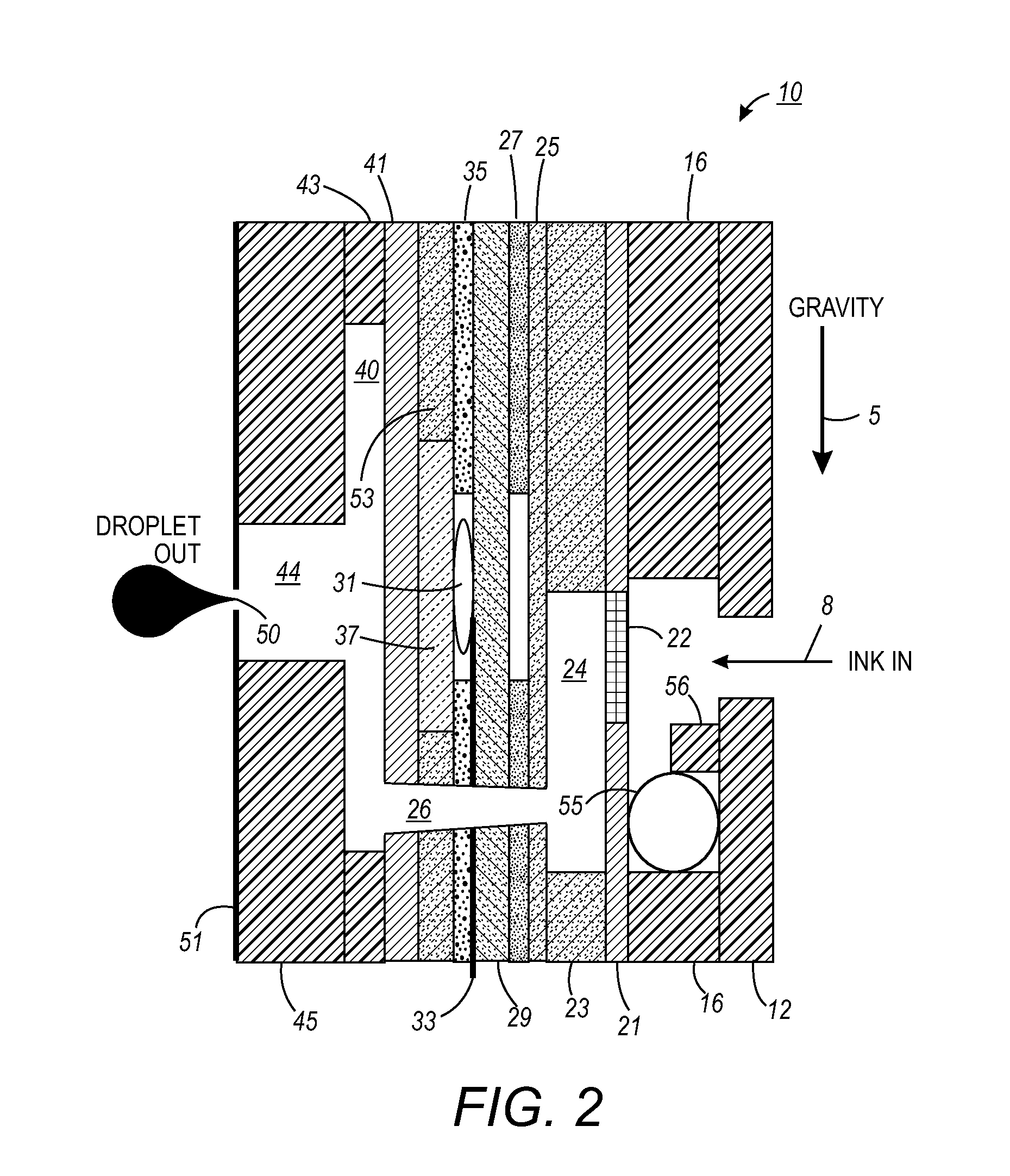
[0008]In answer to this need, provided hereinafter is a method and apparatus that reduces the possibility that narrow, high aspect ratio particles pass through the rock screen by minimizing the number of times the particles interact with the screen. Each interaction is an opportunity for the particle to be positioned in an orientation such that it may pass through the rock screen. Particle traps with “dead zones” are placed adjacent to the rock screen perimeter to collect debris that sloughs off the rock screen. The “dead zones” are sufficiently deep to prevent particles from experiencing flow velocities that would subsequently re-entrain the particles into the main flow and back to the rock screen.

Problems solved by technology

However, high aspect ratio particles that are narrow enough to pass through the rock screen can re-orient in the flow to potentially block a downstream aperture causing print quality defects.
This increases the opportunity for a given particle to orient in such a way that it can pass through the rock screen into the jet and cause print quality defects.

Method used


Image

  • Rock screen with particle trap
  • Rock screen with particle trap
  • Rock screen with particle trap

Examples


Embodiment Construction

[0015]While the disclosure will be described hereinafter in connection with a preferred embodiment thereof, it will be understood that limiting the disclosure to that embodiment is not intended. On the contrary, it is intended to cover all alternatives, modifications and equivalents as may be included within the spirit and scope of the disclosure as defined by the appended claims.

[0016]The disclosure will now be described by reference to preferred ink jet print head embodiments that include a method and apparatus for removing debris that sloughs off a rock screen.

[0017]For a general understanding of the features of the disclosure, reference is made to the drawings. In the drawings, like reference numerals have been used throughout to identify identical elements.

[0018]Referring now to FIG. 1, a print head 10 is shown that includes the improved method and apparatus for removing contamination from inks exiting the print head for improved image quality.

[0019]In FIG. 1, a print head 10 i...


PUM


Abstract

The possibility that narrow, high aspect ratio particles will pass through a rock screen of a print head is reduced by minimizing the number of times the particles interact with the rock screen. Each interaction is an opportunity for the particle to be positioned in an orientation such that it may pass through the rock screen. The reduction in particles passing through the rock screen is achieved by positioning a particle trap adjacent to the rock screen perimeter to collect debris that sloughs off the rock screen.

Description

BACKGROUND[0001]1. Field of the Disclosure[0002]The present disclosure relates to an ink jet recording apparatus and method in which ink droplets are jetted to form images on a recording media, such as, recording sheets, and more particularly, to an ink jet recording apparatus print head that includes a trap positioned within an ink sump and in close proximity to a rock screen to capture particles that slough off the screen.[0003]2. Description of Related Art[0004]Ink jet printers are a well known and widely used form of printed media production. Colorants, usually ink, are fed to an array of micro-processor controlled nozzles on a print head. As the print head passes over the media, colorant is ejected from the array of nozzles to produce the printing on the media substrate.[0005]Computers, fax machines, plotters and printers have presented a growing demand for high quality reproduction and print quality on different recording medium. This demand has necessitated the efficient supp...

Claims


Application Information

Patent Timeline
Patent Type & Authority Patents(United States)
IPC IPC(8): B41J2/165
CPCB41J2/14233B41J2002/14403
Inventor HAYS, ANDREW WSTEPHENS, TERRANCE L
Owner XEROX CORP
Learn More