Data transform apparatus and control method thereof
a data transform and control method technology, applied in the field of data transform technique, can solve problems such as unsuitable for fast transform processing, and achieve the effect of improving such points
- Summary
- Abstract
- Description
- Claims
- Application Information
AI Technical Summary
Benefits of technology
Problems solved by technology
Method used
Image
Examples
first embodiment
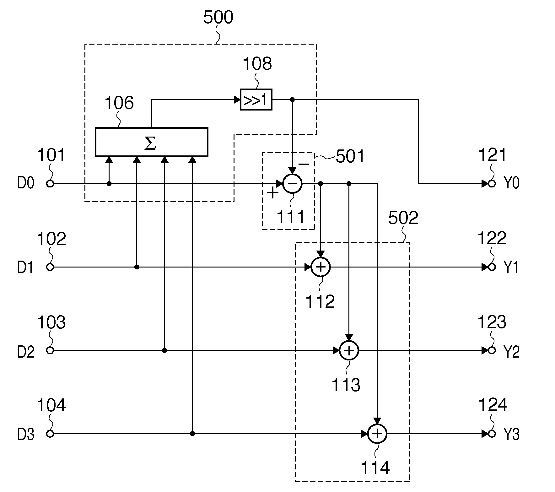
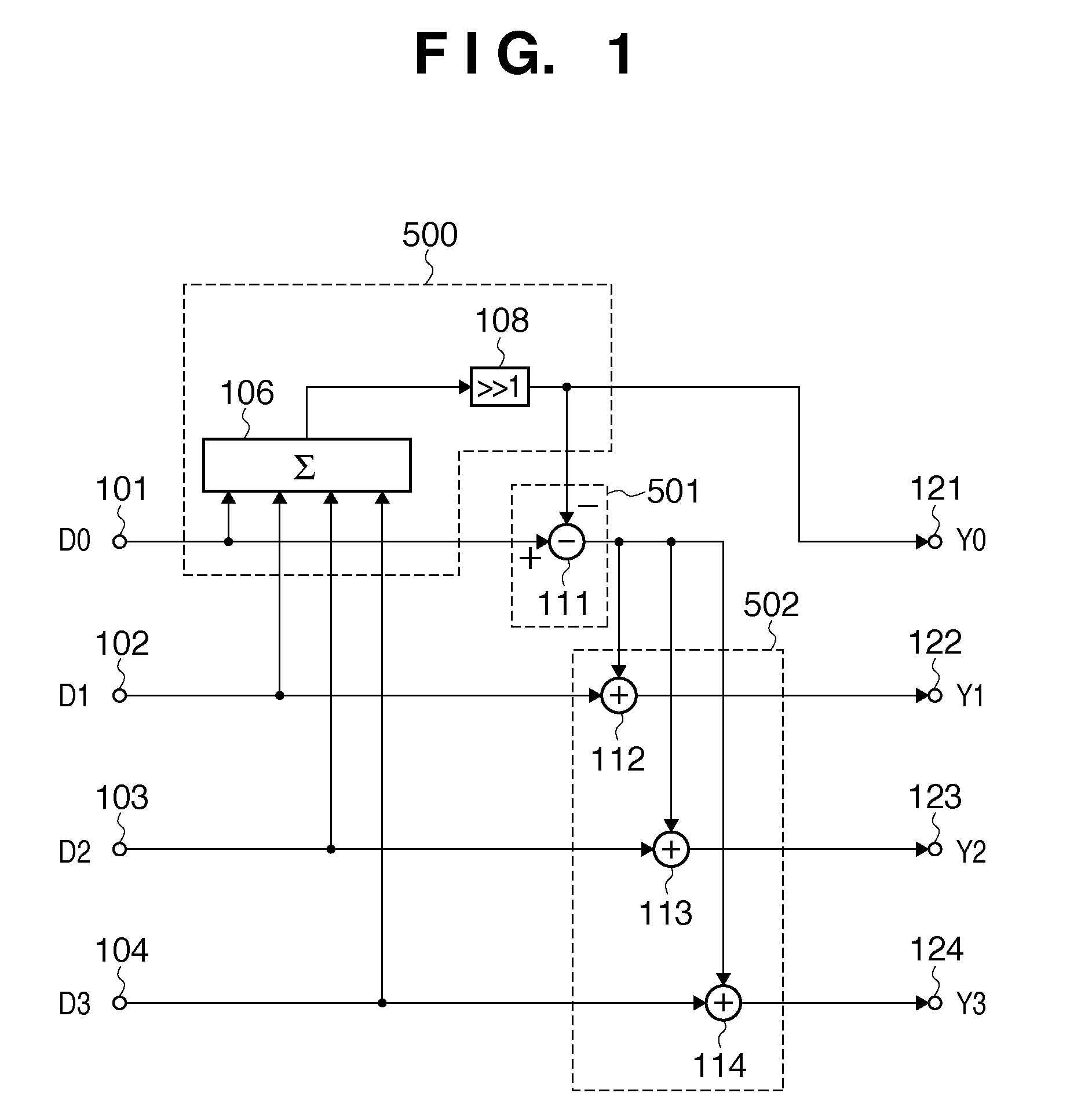
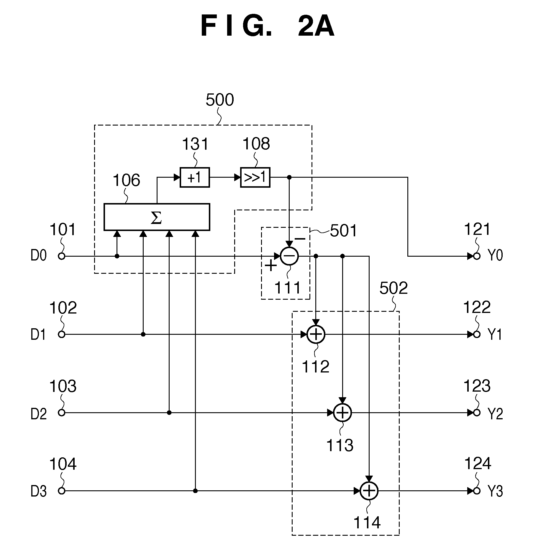
[0073]FIG. 1 shows the circuit arrangement of a data transform apparatus according to the first embodiment. Referring to FIG. 1, reference numerals 101 to 104 denote terminals for inputting four, integer-represented input data D0, D1, D2, and D3. Reference numeral 106 denotes a 4-input summation unit which summates the four data. Reference numeral 108 denotes a shifter which shifts the summation result (addition result) of the summation unit 106 1 bit to the right. Reference numeral 111 denotes a subtractor which generates intermediate data. Reference numerals 112 to 114 denote adders which respectively add the generated intermediate data to the data D1, D2, and D3 of the input data. Reference numerals 121 to 124 denote terminals which output lossless-Hadamard transform results (integer data Y0, Y1, Y2, and Y3). Note that the subtractor 111 and adders 112 to 114 execute integer calculations.
[0074]Although details will be apparent from the following description, a block denoted by re...
second embodiment
Modification of Second Embodiment
[0102]The arrangement of FIG. 3 may be modified to that of FIG. 8. The large differences between FIGS. 8 and 3 are that all of the second to fourth subtractors (reference numerals 312 to 314) in FIG. 3 are replaced by adders 802 to 804, and the following changes (1) and (2) are made.
[0103](1) The subtractor 305 in FIG. 3 subtracts the input data D0 from the output value from the +1 adder 302. However, the subtractor 305 in FIG. 8 subtracts the output value of the summation unit 301 from the input data D0. That is, the sign of the output value of the subtractor 305 in FIG. 8 is inverted from that of the output value of the subtractor 305 in FIG. 3.
[0104](2) In order to execute different round processes to generate a DC coefficient and AC coefficients, if one coefficient is generated by truncating processing, the other is generated by round-up processing. For this purpose, in the arrangement of FIG. 8, a DC coefficient is generated by round-up processi...
third embodiment
[0106]FIG. 4 shows the circuit arrangement of a data transform apparatus according to the third embodiment. Referring to FIG. 4, reference numeral 401 denotes a first adder which adds two data D1 and D2 of four input data; and 402 to 404, second to fourth adders which add input data D0 to respective input data D1, D2, and D3. That is, these adders 402 to 404 serve as an addition data generating unit which generates three sums of two data out of four integer input data.
[0107]Reference numeral 405 denotes a +1 adder which adds “1” to the output value of the first adder 401. Reference numeral 407 denotes a fifth adder which adds the output value from the fourth adder 404 to the addition result of the +1 adder 405. Reference numeral 409 denotes a shifter which shifts the addition result of the adder 407 1 bit to the right. Reference numerals 412 to 414 denote first to third subtractors which respectively subtract the output value from the shifter 409 from the output values of the second...
PUM
 Abstract
Description
Claims
Application Information
 - R&D
- Intellectual Property
- Life Sciences
- Materials
- Tech Scout
- Unparalleled Data Quality
- Higher Quality Content
- 60% Fewer Hallucinations
Browse by: Latest US Patents, China's latest patents, Technical Efficacy Thesaurus, Application Domain, Technology Topic, Popular Technical Reports.
© 2025 PatSnap. All rights reserved.Legal|Privacy policy|Modern Slavery Act Transparency Statement|Sitemap|About US| Contact US: help@patsnap.com


