Printing apparatus and print controlling method

a printing apparatus and control method technology, applied in printing, other printing apparatus, etc., can solve problems such as difficulty in controlling the conveying amount, and achieve the effect of restricting the reduction of throughpu

Inactive Publication Date: 2013-03-05
CANON KK
View PDF11 Cites 5 Cited by
  • Summary
  • Abstract
  • Description
  • Claims
  • Application Information

AI Technical Summary

Benefits of technology

[0013]An object of the present invention is to provide a printing apparatus and a print controlling method which can restrict a reduction of a throughput, in conveying a print medium around a stop-unstable region.
[0022]According to the above structure, the conveying amount of the first conveying operation is maximized and the printing can be completed by plural times of scans after the fourth conveying operation is performed. At the time of performing the second conveying operation after the fourth conveying operation is performed, the printing can be completed with existence of a printing element used for complementing the printing in performing the printing likewise by plural times of the scans while minimizing the number of times of the second conveying operations. Further, the conveying amount of the fourth conveying operation can be made larger than the second conveying amount.
[0023]In consequence, for example, the number of the printing elements is used effectively in the printing of the rear end area of the print medium, so as to restrict a reduction of the throughput of the printing operation.

Problems solved by technology

This event is a phenomenon called a so-called kicking-away, and particularly since a conveying amount of the print medium can not be definitely controlled, this phenomenon causes the difficulty of controlling the conveying amount around a point on the conveying path of the print medium at which the print medium disengages from the state of being held between the conveying roller and the pinch roller at the upstream side.

Method used


Image

  • Printing apparatus and print controlling method
  • Printing apparatus and print controlling method
  • Printing apparatus and print controlling method

Examples


first embodiment

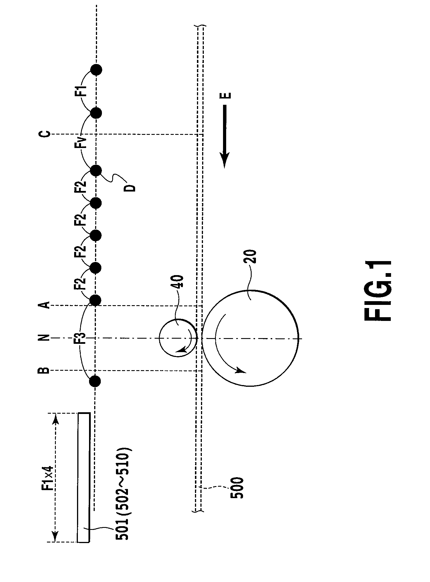
[0043]FIG. 3 is a perspective view showing an ink jet printing apparatus according to an embodiment in the present invention. A printing head (not shown) and ink cartridges 10 are detachably mounted in a carriage 11, and thereby, the printing head scans a print medium such as a paper in a main scan direction and ejects ink on the print medium during the scanning for performing printing. A carriage motor 12 is a drive source for moving the carriage 11. The print paper is conveyed by a given amount in a sub scan direction orthogonal to the main scan direction by a conveying mechanism. An image can be printed on the paper by thus repeating the paper conveyance in the given amount and the scan of the printing head. That is, the printing head in which a plurality of nozzles are lined up scans a plurality of times the print medium with interposing the conveying operation in a printing region between the upstream side and the downstream side, thus completing the printing in a given region ...

second embodiment

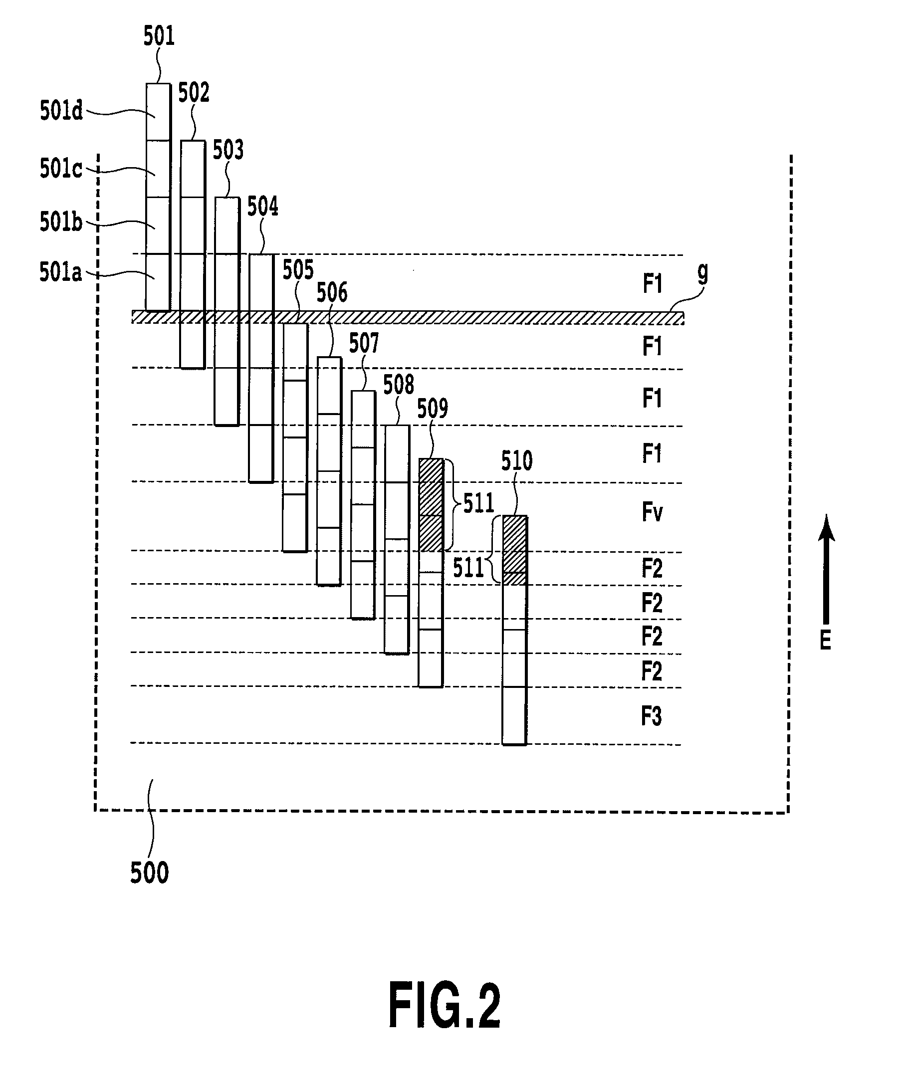
[0060]The conveying control according to a second embodiment of the present invention differs from the first embodiment in that a part of nozzles at the paper rear end side is made to be not used in scans after the conveyance of the conveying amount Fv, in response to a pattern of the mask for each scan used in a multi-pass printing. More specifically, as explained in the first embodiment, when the conveying amount changes F1, Fv and F2 at the time of printing on an area in the vicinity of the rear end of the print medium, a width of an area (hereinafter, also referred to as band) to which printing is completed by plural times of pass (scan) changes in response to the changes of the conveying amount. From this respect, in the masks used in the plural passes, the mutual patterns are required to be complemented for each width of the band. Accordingly, the respective masks of the sizes in accordance with widths of bands are required. In a case where the masks are thus required for the ...

third embodiment

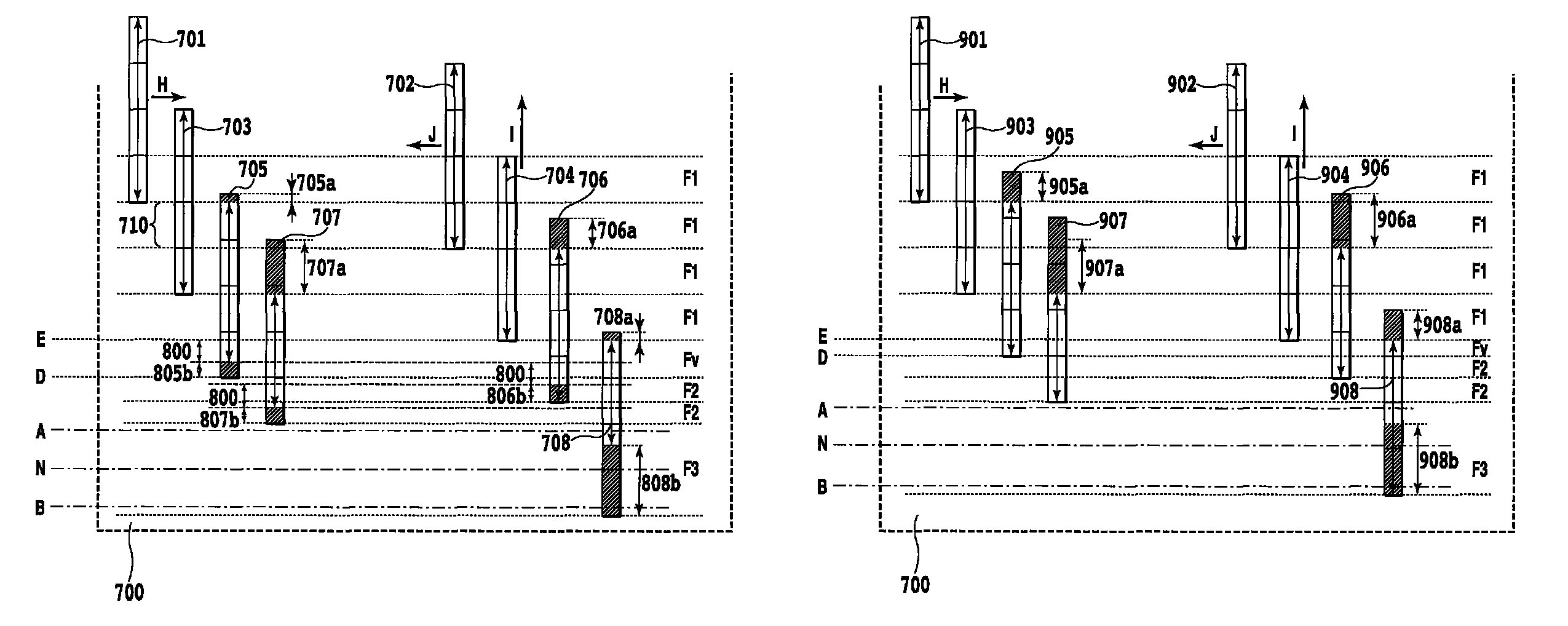
[0091]FIG. 17 is a diagram explaining conveying control according to a third embodiment of the present invention. The present embodiment has a feature that in a case where the conveying amount Fv is smaller than the conveying amount F2, the conveying amount (Fv′) found by adding the conveying amount F2 provided after the conveying amount Fv by one conveyance to the conveying amount Fv is provided, which is 144 nozzles found by “F2+Fv=80+64”. In consequence, in a case where the conveying amount Fv is smaller than the conveying amount F2, the conveyance Fv is absorbed by the conveyance F2 to improve the throughput. In a case where the conveying amount Fv is larger than the conveying amount F2, the control similar to that in FIG. 7 of the first embodiment or in FIG. 12 of the second embodiment is performed. Following expression will be made for a case that the conveying amount Fv corresponds to 64 nozzles.

[0092]Based upon the above conveying control, non-used nozzles 1705a to 1708a, an...


PUM


Abstract

In conveying a print medium before and after a stop-unstable region in a printing apparatus, an image quality is improved while restricting a reduction of a throughput. Specifically a conveying amount is made smaller than a first conveying amount in a usual region. Thereby, the first conveying amount is maximized and the printing in the image region can be complemented by four times of scans after the conveyance of the conveying amount is completed.

Description

BACKGROUND OF THE INVENTION[0001]1. Field of the Invention[0002]The present invention relates to a printing apparatus and a print controlling method, and particularly, to a conveying control of a printing medium before and after timing when the print medium leaves from a conveying roller at the upstream side of a printing region in print-medium conveying.[0003]2. Description of the Related Art[0004]Conveyance of a print medium such as a print paper in a printing apparatus such as an ink jet printer is generally carried out by a conveying mechanism formed of a conveying roller and a pinch roller provided at the upstream side of a printing region in a conveying path and by a conveying mechanism formed of a paper discharging roller and a spur provided at the downstream side thereof. In regard to the print medium conveyance by these mechanisms, for example, when performing a so-called margin-less printing, the conveyance of the print medium may be carried out in a state where the convey...

Claims


Application Information

Patent Timeline
Patent Type & Authority Patents(United States)
IPC IPC(8): B41J29/38
CPCB41J11/425B41J29/02B41J29/38
Inventor NAKAJIMA, YOSHINORIHARA, KATSUSHIHATAKEYAMA, TAKUYA
Owner CANON KK
Why Eureka
Try Eureka