Current sensor

a current sensor and sensor technology, applied in the field of current sensors, can solve the problems of restricted detection accuracy of current, restricted reduction of measurement object magnetic field applied to magnetic electric conversion elements, etc., and achieve the restricted reduction of measurement object magnetic field, and restricted effect of detection accuracy of curren

Active Publication Date: 2014-11-13
DENSO CORP +1
View PDF3 Cites 8 Cited by
  • Summary
  • Abstract
  • Description
  • Claims
  • Application Information

AI Technical Summary

Benefits of technology

[0010]In the above current sensor, since the macroscopic eddy current is small, the variation of the distribution of the measurement object magnetic field flowing through the core caused by the eddy current is restricted. Further, the reduction of the measurement object magnetic field applied to the magnetic electric conversion element is restricted. Furthermore, since the variation of the distribution of the measurement object magnetic field flowing through the core and the reduction of the measurement object magnetic field are restricted, the reduction of the detection accuracy of the current is restricted.

Problems solved by technology

Further, the reduction of the measurement object magnetic field applied to the magnetic electric conversion element is restricted.
Furthermore, since the variation of the distribution of the measurement object magnetic field flowing through the core and the reduction of the measurement object magnetic field are restricted, the reduction of the detection accuracy of the current is restricted.

Method used


Image

  • Current sensor
  • Current sensor
  • Current sensor

Examples


first embodiment

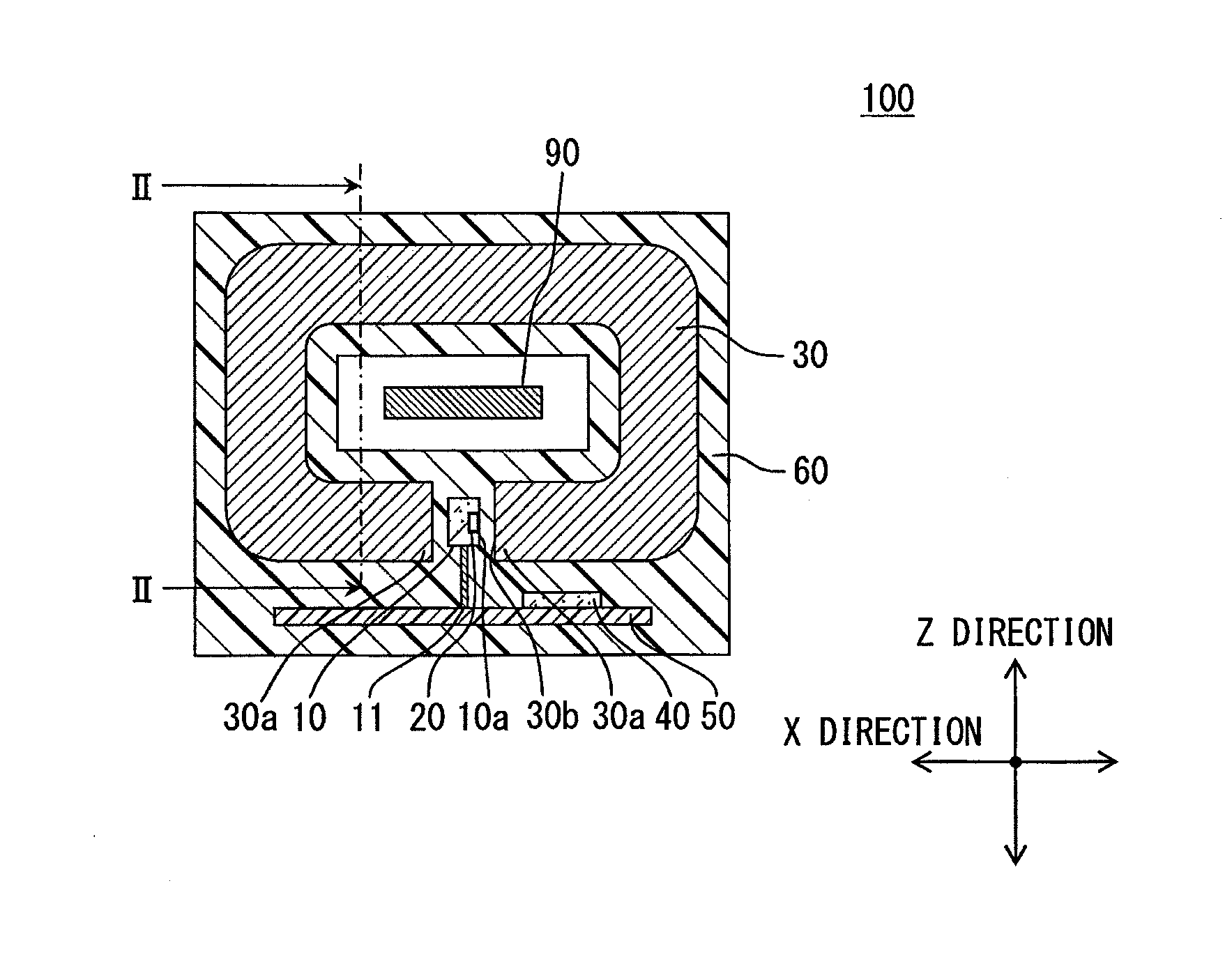
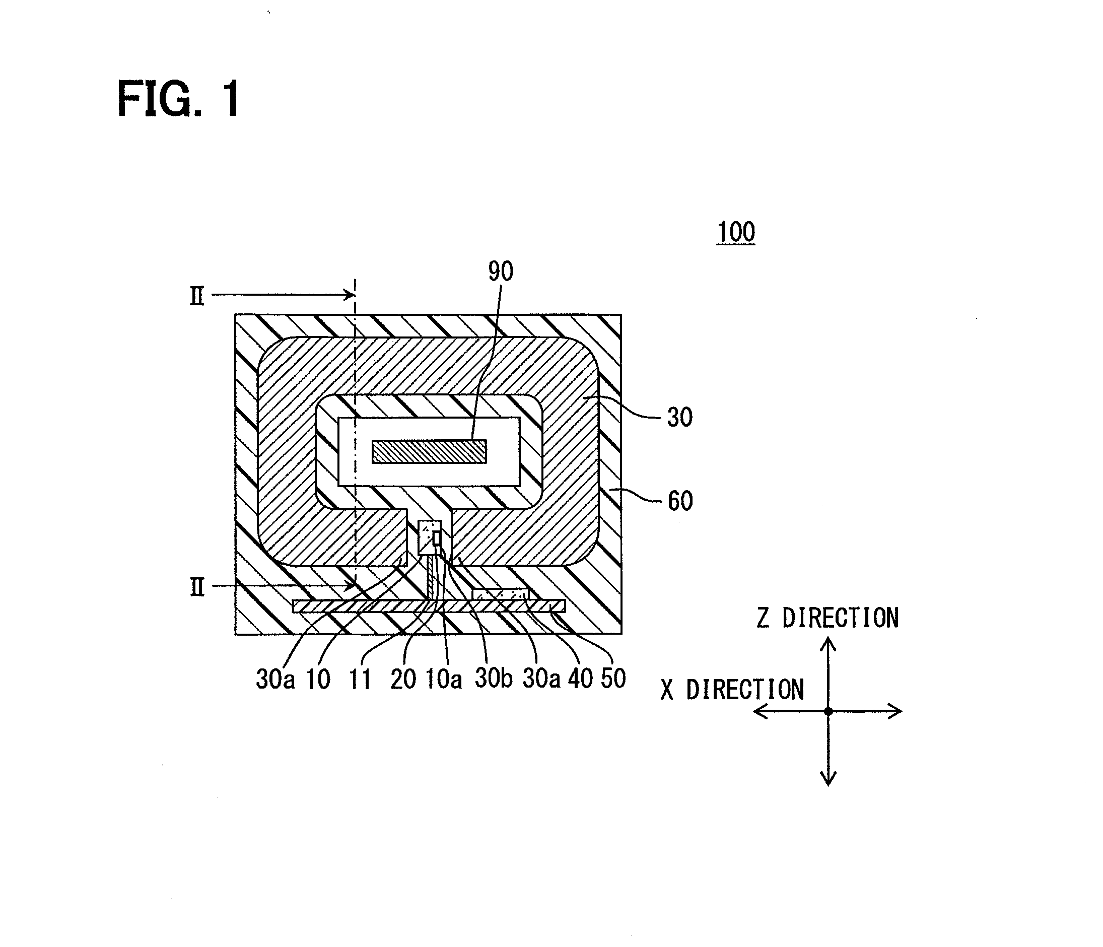
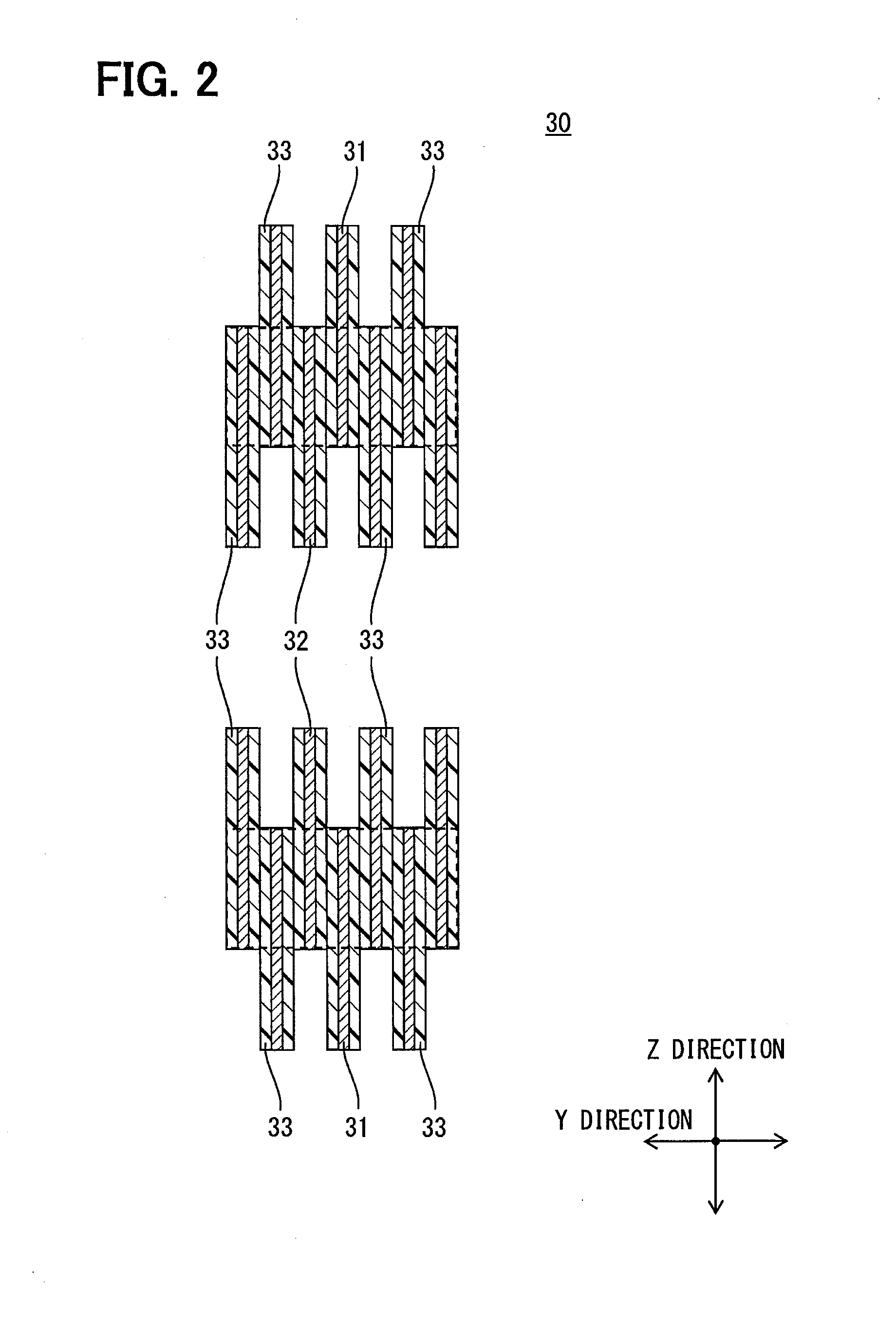
[0027]A current sensor 100 according to the present embodiment will be explained with reference to FIG. 1 to FIG. 3(b). Hereinafter, three directions, which are perpendicular to each other, are defined as a X direction, a Y direction and a Z direction. The Y direction corresponds to the flowing direction. Here, FIG. 1 shows a cross sectional view along a X-Z plane, which is defined by the X direction and the Z direction. FIG. 2 shows a cross sectional view along a Y-Z plane, which is defined by the Y direction and the Z direction. Further, later described FIG. 4 to FIG. 13 are cross sectional views along a Y-Z plane. FIG. 14 is a cross sectional view along a X-Z plane. In FIG. 2, a case 60 is not shown. The cross sectional views of FIG. 4 to FIG. 13 correspond to FIG. 2. Thus, the cross sectional views shown in FIG. 4 to FIG. 13 are cross sectional views taken along line II-II in FIG. 1.

[0028]The current sensor 100 mainly includes a sensor substrate 10, a magneto electric conversion...


PUM


Abstract

A current sensor includes: a magneto electric conversion element; and a magnetic field concentrating core applying a magnetic field caused by a measurement object current to the magneto electric conversion element. A planar shape of the magnetic field concentrating core perpendicular to a current flowing direction is a ring shape with a gap. The magneto electric conversion element is arranged in the gap. A part of a conductor for flowing the current is surrounded by the magnetic field concentrating core. The magnetic field concentrating core includes two first magnetic members and at least one second magnetic member, which are stacked alternately in the current flowing direction. Parts of the two first magnetic members adjacent to each other via the one second magnetic member are opposed to each other through a clearance or an insulator.

Description

CROSS REFERENCE TO RELATED APPLICATION[0001]This application is based on Japanese Patent Applications No. 2011-286446 filed on Dec. 27, 2011, and No. 2012-271568 filed on Dec. 12, 2012, the disclosures of which are incorporated herein by reference.TECHNICAL FIELD[0002]The present disclosure relates to a current sensor including a magneto electric conversion element, and a magnetic field concentrating core for concentrating a measurement object magnetic field caused by a measurement object current and for applying a concentrated measurement object magnetic field to the magneto electric conversion element.BACKGROUND ART[0003]Conventionally, for example, as described in Patent Literature No. 1, Patent Literature No. 1 proposes a current sensor including: a core for providing a first magnetic flux according to the measurement object current, the core formed to have a ring shape with a gap and to surround a part of a current path, in which current (i.e., the measurement object current) a...

Claims


Application Information

Patent Timeline
Patent Type & Authority Applications(United States)
IPC IPC(8): G01R15/18G01R19/00
CPCG01R15/183G01R19/0092G01R15/202G01R15/207H01F38/30
Inventor SAKAI, RYOSUKEKURUMADO, NORIHIRONOMURA, KOUSUKESASADA, ICHIRO
Owner DENSO CORP
Why Eureka
Try Eureka