Fuel vapor treatment apparatus

a technology of vapor treatment apparatus and vaporization chamber, which is applied in the direction of electric control, charge feed system, and addition of non-fuel substances to fuel, etc., can solve the problems of difficult to stabilize the purge concentration, difficult to quickly carry out concentration measurement, and noisy operation of the pump, so as to facilitate air-fuel ratio control, shorten the concentration measurement time of fuel vapor, and reduce noise generation

Inactive Publication Date: 2007-06-21
DENSO CORP
View PDF5 Cites 42 Cited by
  • Summary
  • Abstract
  • Description
  • Claims
  • Application Information

AI Technical Summary

Benefits of technology

[0007]The present invention has been made in view of the foregoing problems and an object of the present invention is to provide a fuel vapor treatment apparatus which stabilizes a concentration of fuel vapor to be treated and restricts generation of noises.
[0008]Another object of the present invention is to provide a fuel vapor treatment apparatus which facilitates an air-fuel ratio control for an internal combustion engine.
[0009]A further object of the present invention is to provide a fuel vapor treatment apparatus which shortens concentration measurement time of fuel vapor to be treated.
[0010]According to an aspect of the present invention, a volume chamber is provided in a purging passage for introducing and purging fuel vapor into an intake system for an internal combustion engine, thus increasing a passage volume of the fuel vapor. Thereby, the fuel vapor is diffused due to flowing from the upstream side of the volume chamber in the purging passage into the volume chamber and therefore, the concentration of the fuel vapor is diluted. Therefore, even if the fuel vapor concentration at the upstream side of the volume chamber in the purging passage changes with time, since the change of the fuel vapor concentration with time in the volume chamber is averaged, the fuel vapor concentration at the downstream side of the volume chamber in the purging passage becomes stable. Further, a pump for generating a fluid flow in the purging passage forcibly generates a flow of the fuel vapor flowing into the volume chamber, facilitating stabilization of the fuel vapor concentration and forcibly purging the fuel vapor of the stabilized concentration. In addition, since the pump is received in the volume chamber, an operating sound of the pump can be blocked by the walls of the volume chamber.

Problems solved by technology

However, in the apparatus for communicating a purging passage with a fuel tank through a canister, which is disclosed in JP-2002-332921A, since the concentration of the fuel vapor desorbed from the canister and flowing into the purging passage changes with time in response to a remaining fuel adsorption quantity in the canister, it is difficult to stabilize the purge concentration.
Further, when the pump is located as exposed to an outside, an operating sound of the pump may be the cause of noises.
Yet, since the detection quantity is easily changed due to the fluctuation of an intake vacuum, this makes it more difficult to promptly carry out the concentration measurement.

Method used


Image

  • Fuel vapor treatment apparatus
  • Fuel vapor treatment apparatus
  • Fuel vapor treatment apparatus

Examples


first embodiment

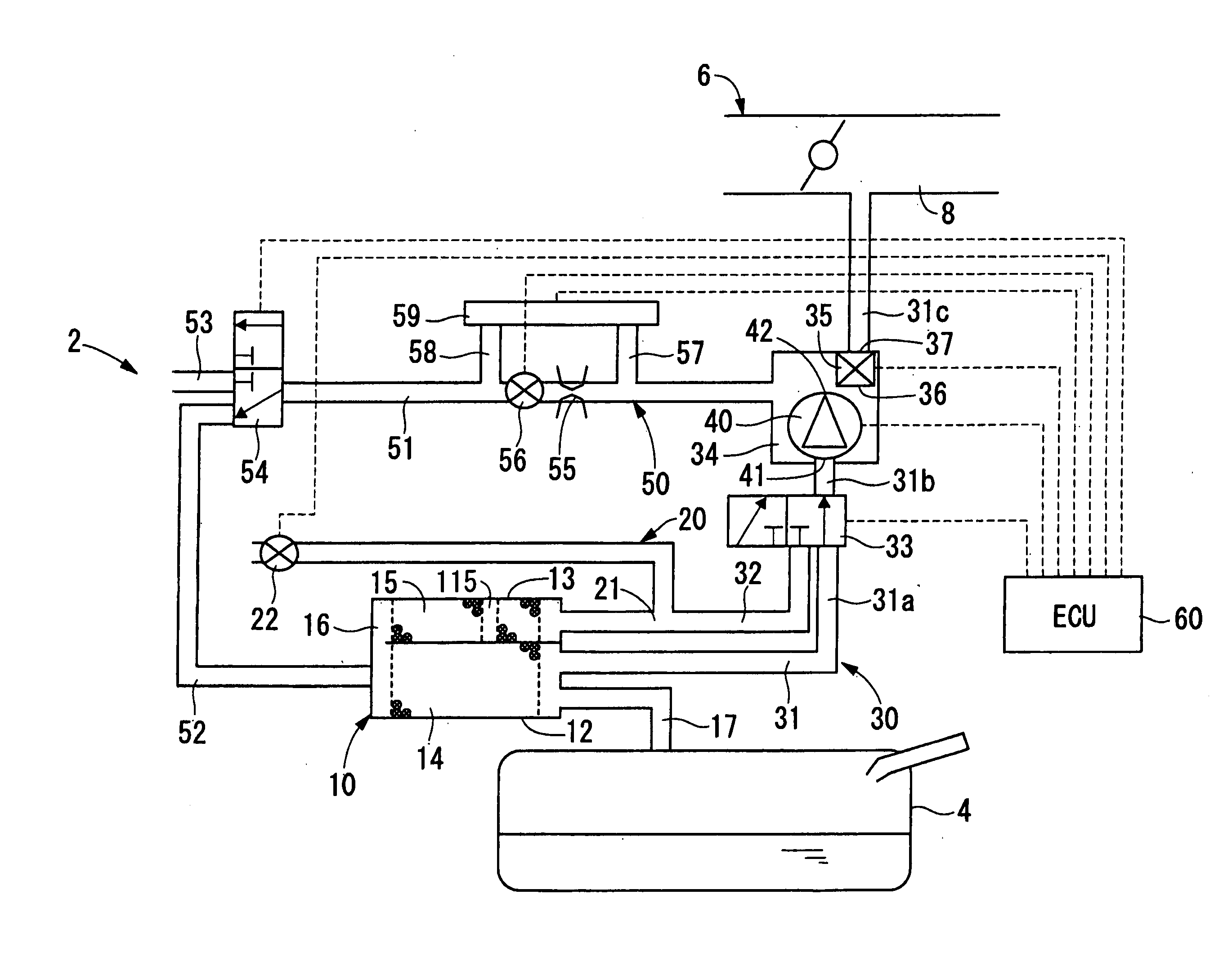
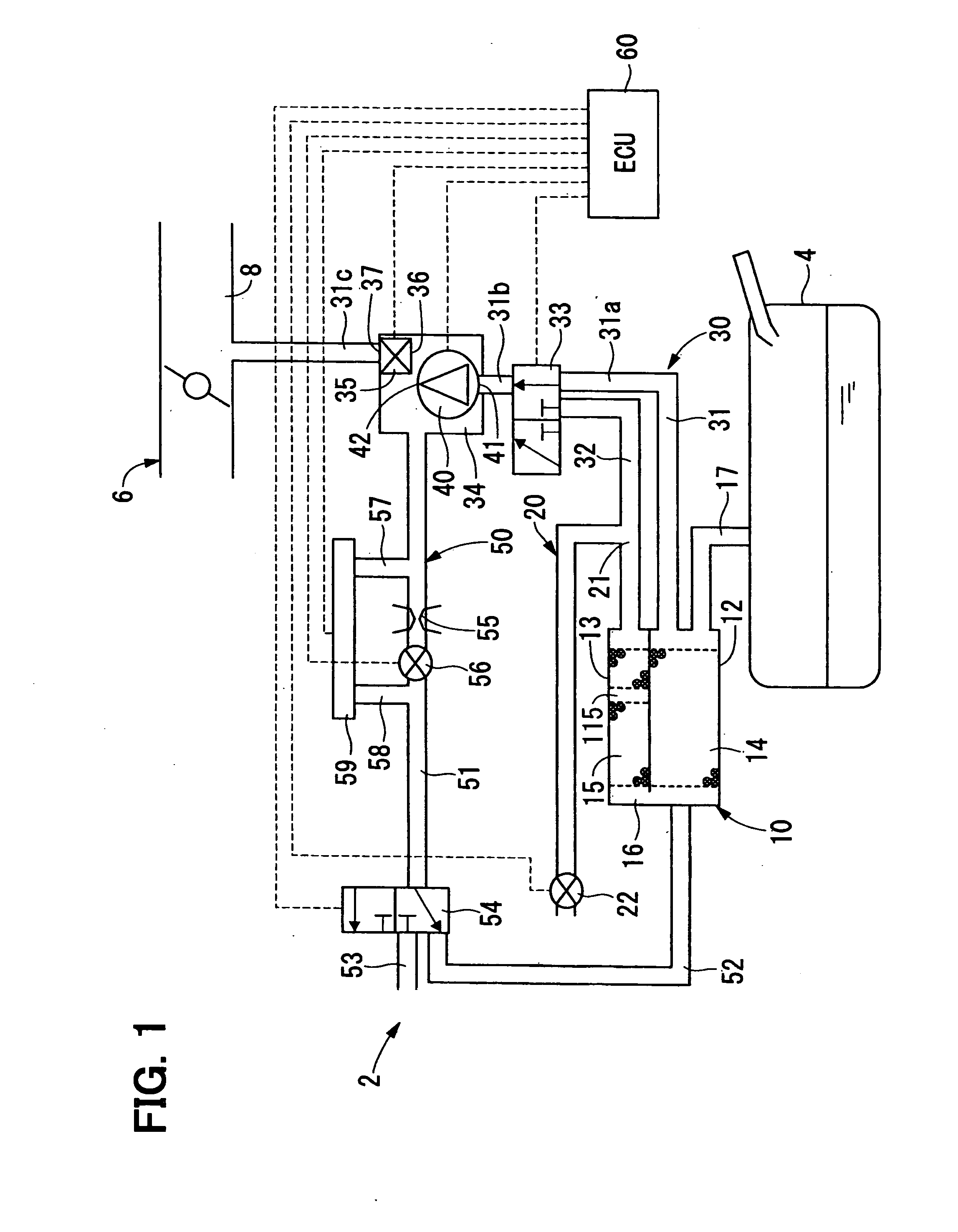
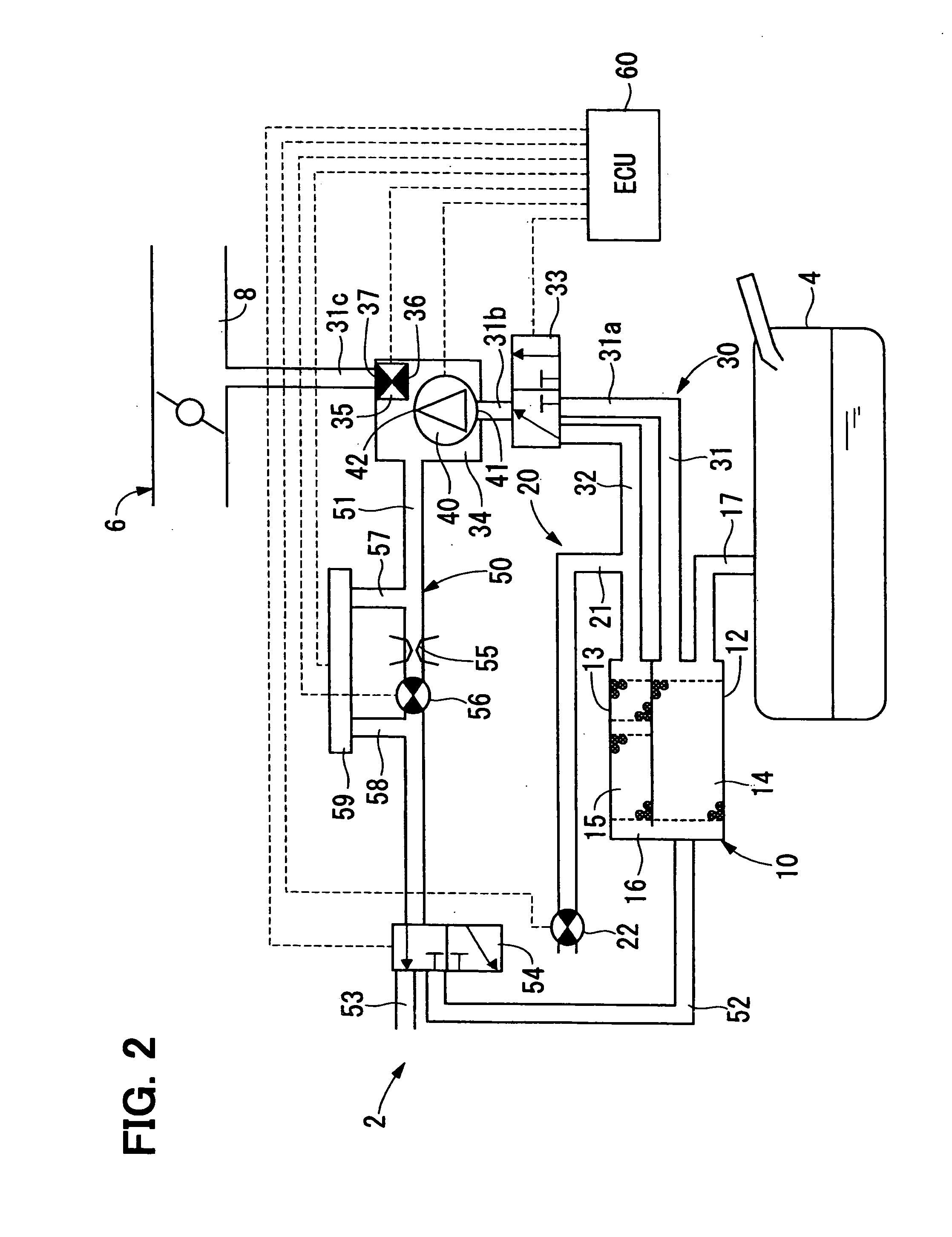
[0028]FIG. 1 shows a fuel vapor treatment apparatus 2 in a first embodiment of the present invention. The fuel vapor treatment apparatus 2 treats produced in a fuel tank 4 and feeds the treated fuel vapor to an internal combustion engine 6. The fuel vapor treatment apparatus 2 is provided with a canister 10, an atmospheric release control system 20, a purging system 30, a pump 40, a detection system 50, and an electronic control unit (ECU) 60.

[0029]The canister 10 has two adsorbing parts 12 and 13 formed by dividing its inside with a partition wall. Each of the adsorbing parts 12 and 13 is filled with adsorbing materials 14 and 15 respectively, made of active carbon, silica gel, or the like. Each of the adsorbing parts 12 and 13 is in communication with each other through a communicating space 16. The main adsorbing part 12 is communicated with the fuel tank 4 through a tank passage 17 and also is communicated with a purging passage 31 of the purging system 30 at the opposite side t...

second embodiment

[0059]As shown in FIG. 12, a second embodiment shows a modification of the first embodiment.

[0060]More specially, in a fuel vapor treatment apparatus 100 of the second embodiment, a detection passage 110 is communicated with the third passage part 31c in the purging passage 31 located at the downstream side of the volume chamber 34 and the purge control valve 120 is provided in the third passage part 31c placed outside of the volume chamber 34.

[0061]In the second embodiment, the concentration measurement process, the purging process and the leakage inspection process similar to those in the first embodiment are executed. Therefore, at the time of executing each process, generation of noises due to the operation of the pump 40 can be restricted.

[0062]According to the second embodiment, in the purging passage 31 the purge control valve 35 is designed to be located at an opposing side to the canister 10 in such a way as to sandwich the volume chamber 34. Therefore, the pressure fluctua...

third embodiment

[0063]As shown in FIG. 13, a third embodiment shows a modification of the second embodiment.

[0064]More specially, in a fuel vapor treatment apparatus 150 of the third embodiment, the second and third passage parts 31b and 31c of the purging passage 31 are directly communicated to each other and a detection passage 160 is communicated with the boundary part between the second and third passage parts 31b and 31c. Further, a volume chamber 180 for receiving a pump 170 therein is provided in the detection passage 160 between the purging passage 31 and the first pressure-introducing passage 57. The volume chamber 180 has a cross section greater than that of the detection passage 160 as shown in FIG. 13 to secure a passage volume enlarged to the detection passage 160. A suction port 171 of the pump 170 is communicated at the side of the purging passage 31 from the volume chamber 180 with the detection passage 160 and a discharge port 172 of the pump 170 is open in the inside of the volume...


PUM


Abstract

A fuel vapor treatment apparatus is provided with a purging passage for introducing and purging fuel vapor produced in a fuel tank to an intake system for an internal combustion engine, a volume chamber located in the purging passage for enlarging a passage volume and a pump received in the volume chamber for generating a fluid flow in the purging passage.

Description

CROSS-REFERENCE TO RELATED APPLICATION[0001]This application is based on Japanese Patent Application No. 2005-366122 filed on Dec. 20, 2005, the disclosure of which is incorporated herein by reference.FIELD OF THE INVENTION[0002]The present invention relates to a fuel vapor treatment apparatus which treats fuel vapor produced in a fuel tank.BACKGROUND OF THE INVENTION[0003]There is conventionally known a fuel vapor treatment apparatus in which a fluid flow is generated by a pump in a purging passage for introducing fuel vapor produced in a fuel tank to an intake system for an internal combustion engine, forcibly purging the fuel vapor (for example, refer to JP-2002-332921A, U.S. Pat. No. 6,695,895). In such a fuel vapor treatment apparatus, in order to avoid the state where an air-fuel ratio control for the engine is complicated due to the fluctuation of a purge concentration of the fuel vapor, it is desirable to stabilize the purge concentration.[0004]In addition, there is known a ...

Claims


Application Information

Patent Timeline
Patent Type & Authority Applications(United States)
IPC IPC(8): F02M25/08
CPCF02D41/0045F02M25/0809F02M25/0836F02M25/089
Inventor KOYAMA, NOBUHIKO
Owner DENSO CORP
Why Eureka
Try Eureka