Method of imparting twist to optical fiber

Inactive Publication Date: 2006-06-22
CORNING INC
View PDF21 Cites 43 Cited by
  • Summary
  • Abstract
  • Description
  • Claims
  • Application Information

AI Technical Summary

Benefits of technology

[0008] The present invention relates to methods for producing low PMD fiber via imparting a twist to the optical fiber. In one aspect of the present invention, a glass fiber is pulled or drawn from an optical fiber preform, for example by a tractor device which pulls the optical fiber from the preform. At some point after the tractor has pulled the optical fiber from the preform, and the fiber has cooled to the point where

Problems solved by technology

However, in practice, optical fibers are not perfectly circularly symmetric.
PMD is well known to severely impair transmission of optical signals at relatively hi

Method used


Image

  • Method of imparting twist to optical fiber
  • Method of imparting twist to optical fiber
  • Method of imparting twist to optical fiber

Examples


Example

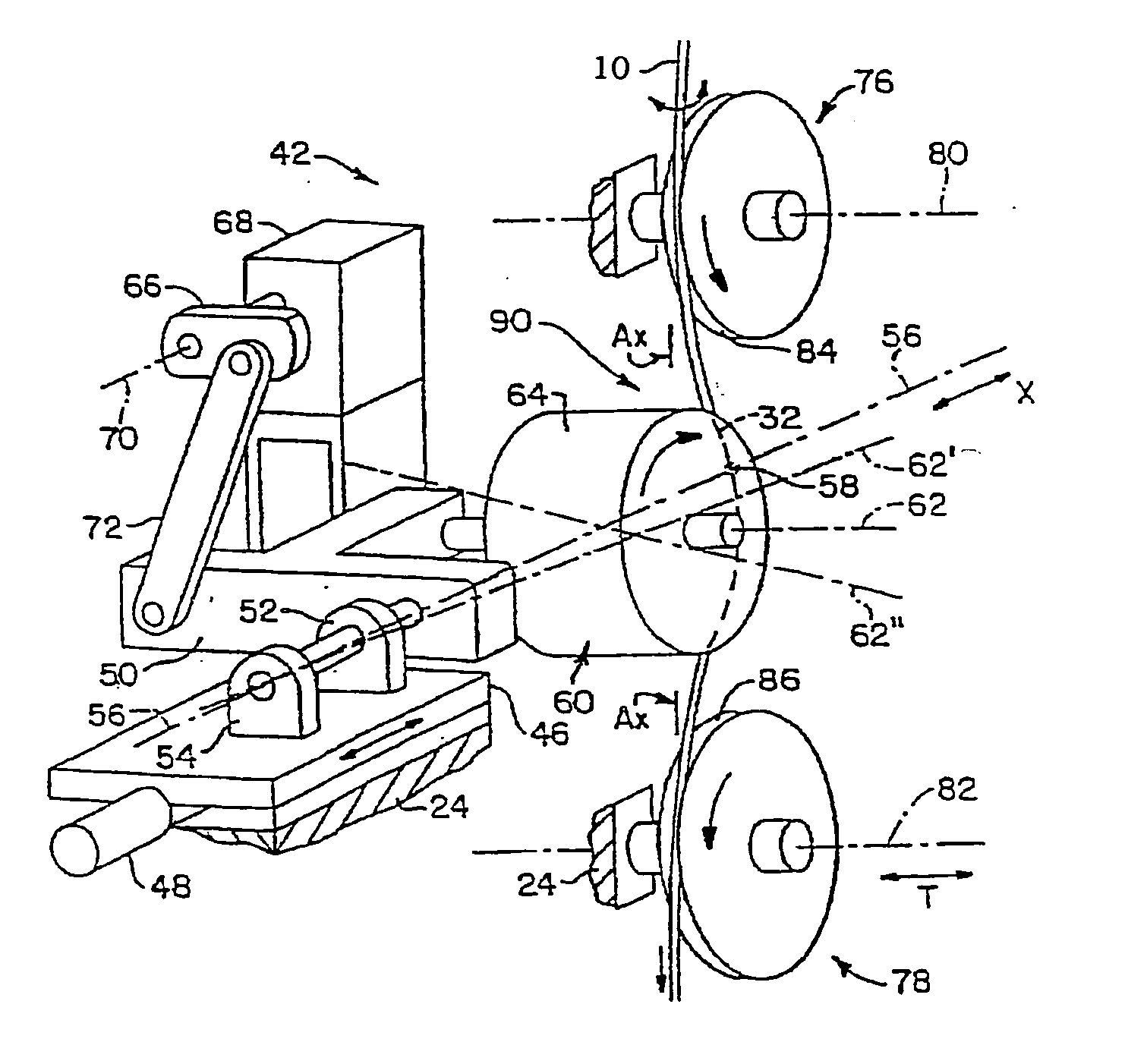
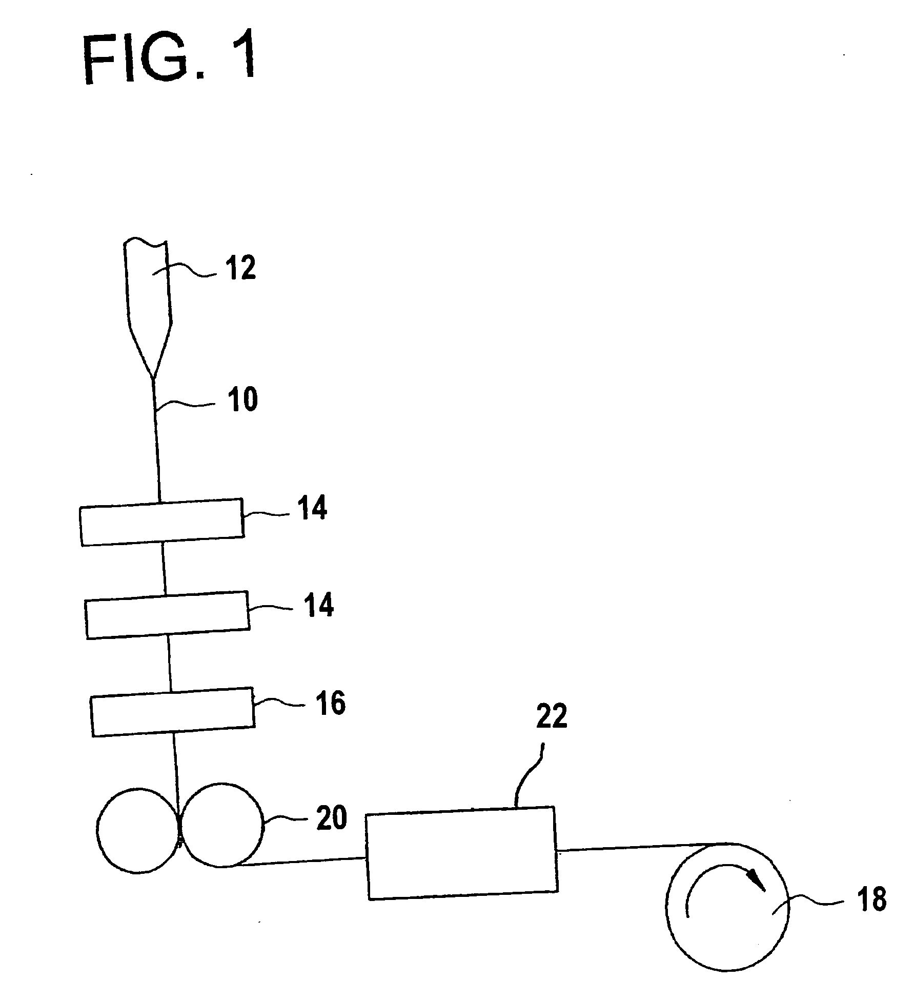
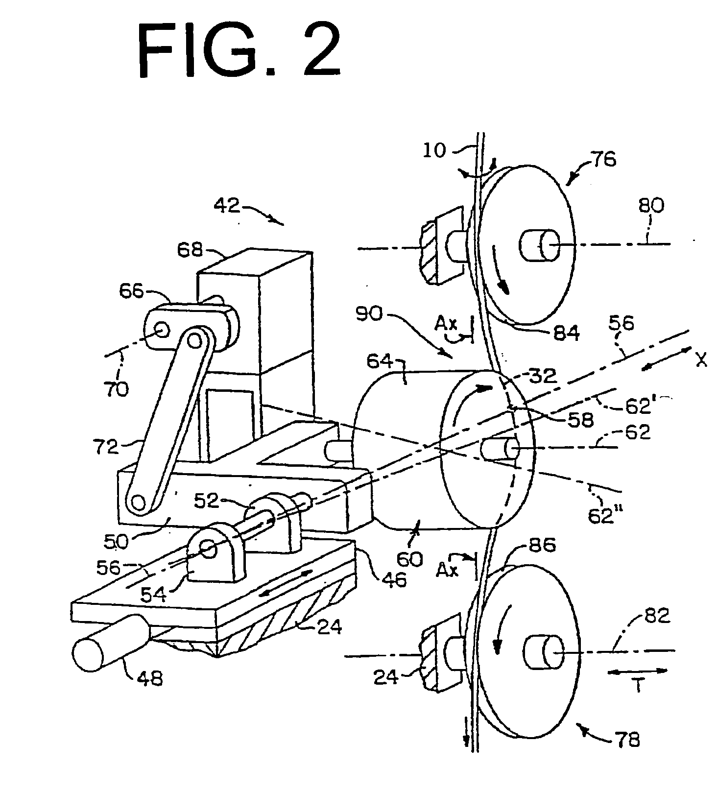
[0023] Whenever possible, the same reference numerals will be used throughout the drawings to refer to the same or like parts. One exemplary apparatus for carrying out the methods of the present invention is illustrated in FIGS. 1 and 2. FIG. 1 illustrates a typical fiber draw operation schematically. The fiber draw operation illustrated in FIG. 1 comprises four major steps: (1) drawing fiber 10 from a preform 12 disposed in a draw furnace; (2) passing fiber 10 through at least one coater 14 for coating fiber 10 with at least one UV curable acrylate coating; (3) curing the coating by passing the coated fiber through at least one curing element 16 and (4) winding the coated fiber onto a spool 18 for storage and transport. The winding portion starts at the tractor 20. In the embodiment illustrated, the tractor comprises a pair of wheels between which the fiber is pinched. However, other variations of tractors could be employed, for example where the fiber is pinched between a belt and...


PUM

PropertyMeasurementUnit
Timeaaaaaaaaaa
Distanceaaaaaaaaaa
Distanceaaaaaaaaaa

Abstract

A method for producing low-PMD fiber, in which a glass fiber is drawn from an optical fiber perform by a tractor which pulls such optical fiber from said perform; subsequent to said tractor pulling the fiber is twisted about its axis to increase the magnitude of twist which is imparted to said fiber. The fiber is then wound onto a fiber storage spool such that at least a portion of the twist imparted to said optical fiber is retained while said fiber is wound on said spool.

Description

BACKGROUND OF THE INVENTION [0001] 1. Field of the Invention [0002] The present invention relates generally to methods and apparatuses for imparting fiber twist, and more particularly, to methods and apparatuses for imparting mechanical twist in optical fiber to reduce polarization mode dispersion (PMD) and to ensure optical fiber quality. [0003] 2. Technical Background [0004] Light traveling in an optical fiber has two polarization modes. For optical fibers that are perfectly circularly symmetric in both geometry and internal and applied stress, operation at a wavelength or in a wavelength range which is regarded as “single-moded” actually supports two orthogonal polarization modes, wherein the two polarization modes are degenerate, propagate with the same group velocity and have no time delay after traveling the same distance in the fiber. However, in practice, optical fibers are not perfectly circularly symmetric. For example, imperfections such as geometric and form deformation ...

Claims


Application Information

Patent Timeline
IPC IPC(8): G02B6/02
CPCC03B37/02745C03B37/032C03B37/12C03B2203/19C03B2203/36C03B2205/06G02B6/02285G02B6/278
Inventor CHEN, XINLI, MING-JUNHERON, NICOL A.SWECKER, JEANNE L.ZHOU, NAIYUE
Owner CORNING INC
Why Eureka
Try Eureka