Ion mobility separation system with rotating field confinement

a separation system and rotating field technology, applied in particle separator tube details, electron/ion optical arrangements, instruments, etc., can solve the problems of limited mobility resolution of the tims system and thus the scan time, ion loss, and limited ability of confinement systems

Pending Publication Date: 2022-02-24
BRUKER DALTONIK GMBH & CO KG
View PDF6 Cites 0 Cited by
  • Summary
  • Abstract
  • Description
  • Claims
  • Application Information

AI Technical Summary

Benefits of technology

[0008]In accordance with a first aspect of the present invention, a trapped ion mobility separator has an ion path along which ions travel through a gas from an entrance to an exit along a first axial direction relative to a central axis of the ion path. A first force-generating apparatus is provided that exerts a first force on the ions in the first axial direction. A second force-generating apparatus is also provided, and exerts a second force on the ions in a second axial direction opposite to the first axial direction. At least one of the first and second forces varies spatially along the first axial direction such that the ions are trapped and separated by ion mobility along the first axial direction during an accumulation phase. During a subsequent elution phase, at least one of the first and second forces is varied to increase a magnitude of the first force relative to the second force over time, such that the ions are progressively driven to the exit of the ion path as a function of ion mobility. A rotating confinement field-generating apparatus is also provided that generates a radially-inhomogeneous electrical potential that exerts a confinement force on the ions in a radial direction toward the central axis, with relative minima and maxima of the electrical potential rotating about the central axis as a function of time.

Problems solved by technology

Thus, the low pressure operation limits the mobility resolution of the TIMS system and thus the scan time.
Systems that operate at pressures as high as 5000 Pa have been developed but, as the pressure is increased further, problems arise from ion loss due to a radial deviation of ions within the TIMS, as ions are destroyed due to their making contact with surrounding surfaces.
However, these radial confinements systems are limited in their ability to prevent ion loss and this, in turn, limits the performance of TIMS systems in general.

Method used


Image

  • Ion mobility separation system with rotating field confinement
  • Ion mobility separation system with rotating field confinement
  • Ion mobility separation system with rotating field confinement

Examples


Embodiment Construction

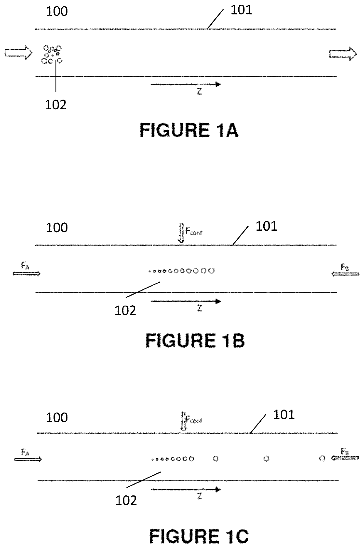
[0065]FIGS. 1A-1C show schematically three stages of operation for a general version of a trapped ion mobility separator 100 according the invention. The trapped ion mobility separator 100 includes an ion channel 101, which typically includes a structure that surrounds the ion path and includes electrodes for generating electric fields within the ion channel 101. As shown in FIG. 1A, ions 102 enter from one side of the channel 101, and will eventually travel to the opposite side of the channel, being temporarily trapped along the way at mobility dependent positions. The ions 102 are the molecular constituents of a sample material of interest, which have been ionized and introduced to the ion channel, typically from an ionization source of a known type, such as an electrospray or MALDI (matrix-assisted laser desorption ionization) type ion source or CI (chemical ionization) ion source. The ions 102 enter the channel 101 having arbitrary position and velocity, but will be separated by...


PUM

PropertyMeasurementUnit
pressureaaaaaaaaaa
pressureaaaaaaaaaa
pressuresaaaaaaaaaa

Abstract

An ion mobility separator includes an ion path with a central axis along which ions travel, the ion path containing a gas. A first force is applied to the ions in a first axial direction, and a second force that varies spatially along the ion path is applied to the ions in second axial direction opposite the first axial direction. A rotating confinement field has a radially-inhomogeneous electric potential with relative maxima and minima that rotate about the central axis as a function of time, the confinement field exerting a radial confinement force on the ions in a radial direction toward the central axis. The ion mobility separator may be operated at elevated pressures including ambient pressure and higher. The first and/or second axial forces may be a constant or gradient gas flow, a constant or gradient electric field or an axial component of the rotating confinement field.

Description

BACKGROUND OF THE INVENTIONField of the Invention[0001]This invention relates generally to the field of ion mobility spectrometry and, more specifically, to trapped ion mobility spectrometry (TIMS), and to hybrid systems coupling ion mobility spectrometry and mass spectrometry.Description of the Related Art[0002]Ion mobility spectrometry (IMS) is an analytical technique that is used to investigate the mobility of ions in a buffer gas and to separate them according to their mobility. An inherent feature of ion mobility spectrometry is that the mobility of ions in a buffer gas depends on molecular geometries of the ions such that it is often possible to resolve and thus separate isomers or conformers that cannot be resolved by mass spectrometry. Many applications also take advantage of the ability to determine the cross section of an analyte ion from its measured mobility. Knowledge of cross sections has proven to be significant in many areas including identifying compound class and d...

Claims


Application Information

Patent Timeline
Patent Type & Authority Applications(United States)
IPC IPC(8): G01N27/62H01J49/06H01J49/10H01J49/24H01J49/00H01J49/42
CPCG01N27/622H01J49/06H01J49/4215H01J49/24H01J49/004H01J49/10H01J49/0027H01J49/0031H01J49/063G01N27/62G01N27/623H01J49/00H01J49/065
Inventor PRABHAKARAN, ANEESH
Owner BRUKER DALTONIK GMBH & CO KG
Why Eureka
Try Eureka