

System and method for sinusoidal output and integrated EMC filtering in a motor drive
- Summary
- Abstract
- Description
- Claims
- Application Information
AI Technical Summary
Benefits of technology
Problems solved by technology
Method used
Image

Examples
first embodiment
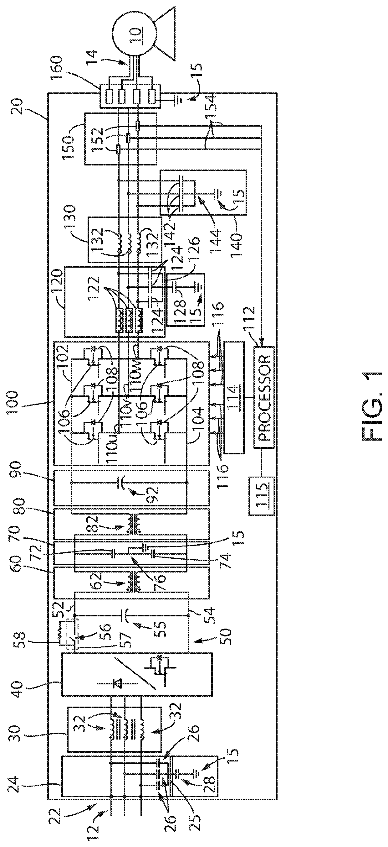
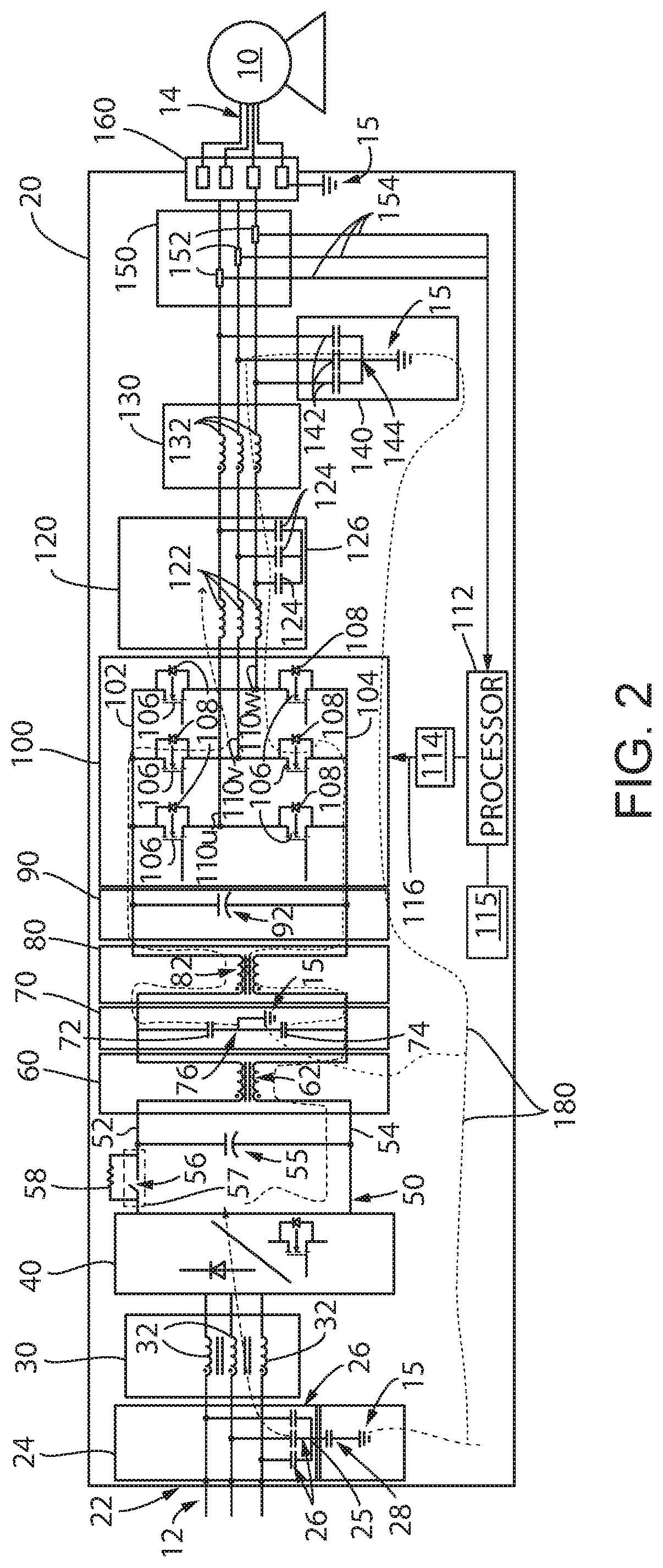
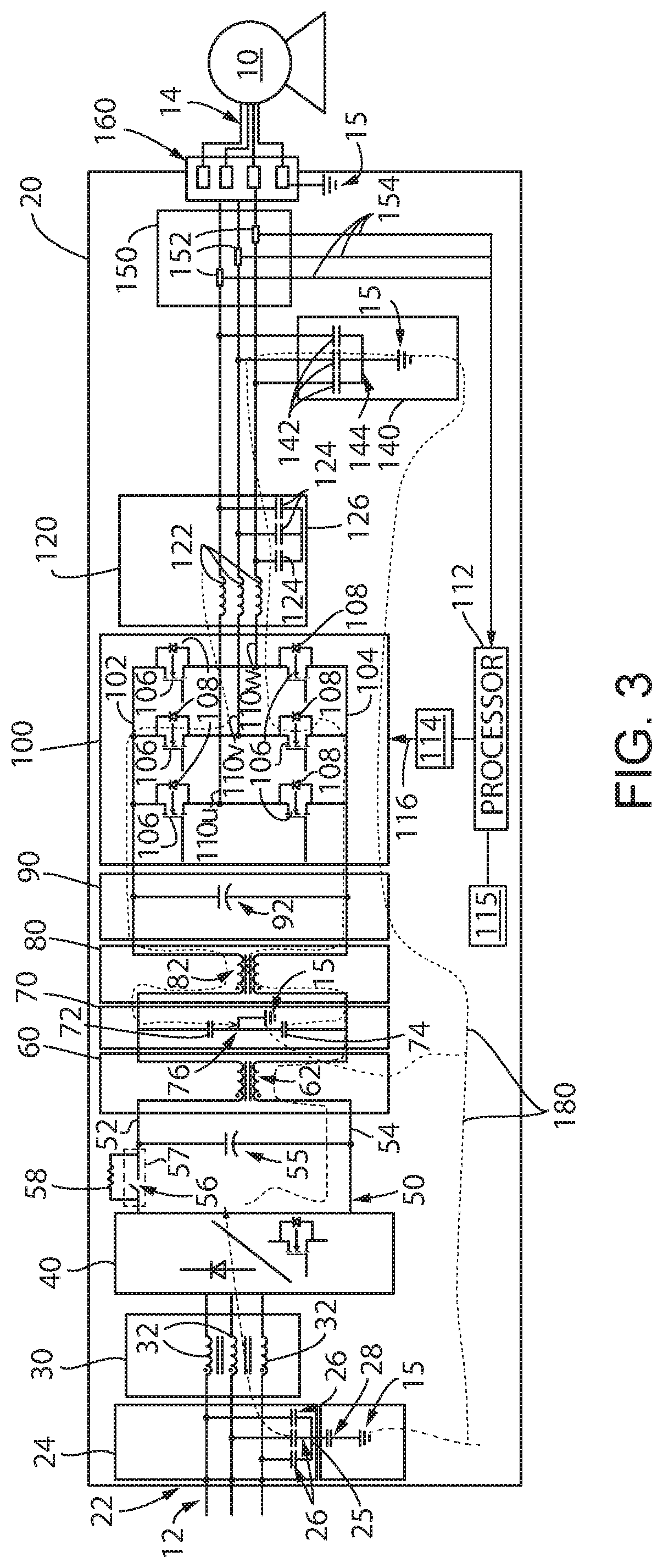
[0043]Turning initially to FIG. 1, a motor drive 20 incorporating EMI filtering and producing a sinusoidal voltage output is illustrated. An AC voltage 12 is provided at an input 22 to the motor drive 20. According to the illustrated embodiment, the AC voltage 12 is a three-phase AC input voltage. The motor drive supplies a sinusoidal output voltage from an output 160 of the motor drive to a motor 10 operatively connected to the motor drive 20 via a cable 14. The output voltage is a three-phase AC output voltage with individual conductors shown extending between the motor 10 and drive 20 for each phase as well as for a ground conductor. It is understood that the illustrated conductors may be combined within a cable 14, run as individual conductors, or a combination thereof according to the application requirements.
[0044]After the input 22 of the motor drive 20, a first filter 24 and a second filter 30 are connected in series between the input 22 and a converter section 40 of the mot...
second embodiment
[0092]In FIG. 22, the radiated emissions shield 320 is illustrated mounted to an inside surface of a housing 310 for the motor drive 20. The housing 310 may mount over the chassis 300 shown in FIG. 21 and position the radiated emissions shield 320 with respect to the primary PCB 330. The shield 320 is tied to a common connection, such as a ground connection, in order that currents induced in the shield are carried to the ground connection. The radiated emissions shield 320 may be, for example, a metal plate mounted to the interior surface of the housing 310. Optionally, the radiated emissions shield 320 may be a conductive coating applied to surface.
[0093]Turning next to FIG. 23, the orientation of the radiated emission shield 320 with respect to the primary PCB 330 is illustrated. The radiated emissions shield 320 is shown covering at least a portion of the primary PCB 330. Electrical components located behind the shield 320 include, for example, the driver module 114, inverter sec...
PUM
 Abstract
Description
Claims
Application Information