
Method for controlling a power split continuously variable transmission and a power split continuously variable transmission

power split technology, applied in the direction of transmission elements, fluid gearings, gearing control, etc., can solve problems such as power loss, and achieve the effect of increasing the efficiency of a continuously variable transmission

Inactive Publication Date: 2015-01-15
VOLVO CONSTR EQUIP
View PDF17 Cites 8 Cited by
  • Summary
  • Abstract
  • Description
  • Claims
  • Application Information

AI Technical Summary

Benefits of technology

The patent text describes a method for reducing power loss in a lock up state in a power split continuously variable transmission. The method involves simultaneously reducing the displacement of two variable displacement hydrostatic machines to reduce fluid flow losses. This results in a reduction of power loss and associated flow losses. The method can be used in both the first and second operating modes of the transmission, and can be initiated as soon as the lock up state is initiated. The invention also relates to a power split continuously variable transmission including a variator unit and a planetary gear unit.

Problems solved by technology

The flow between the first and second variable displacement hydrostatic machines results in a loss of power, due to fluid flow losses.

Method used


Image

  • Method for controlling a power split continuously variable transmission and a power split continuously variable transmission
  • Method for controlling a power split continuously variable transmission and a power split continuously variable transmission
  • Method for controlling a power split continuously variable transmission and a power split continuously variable transmission

Examples


Embodiment Construction

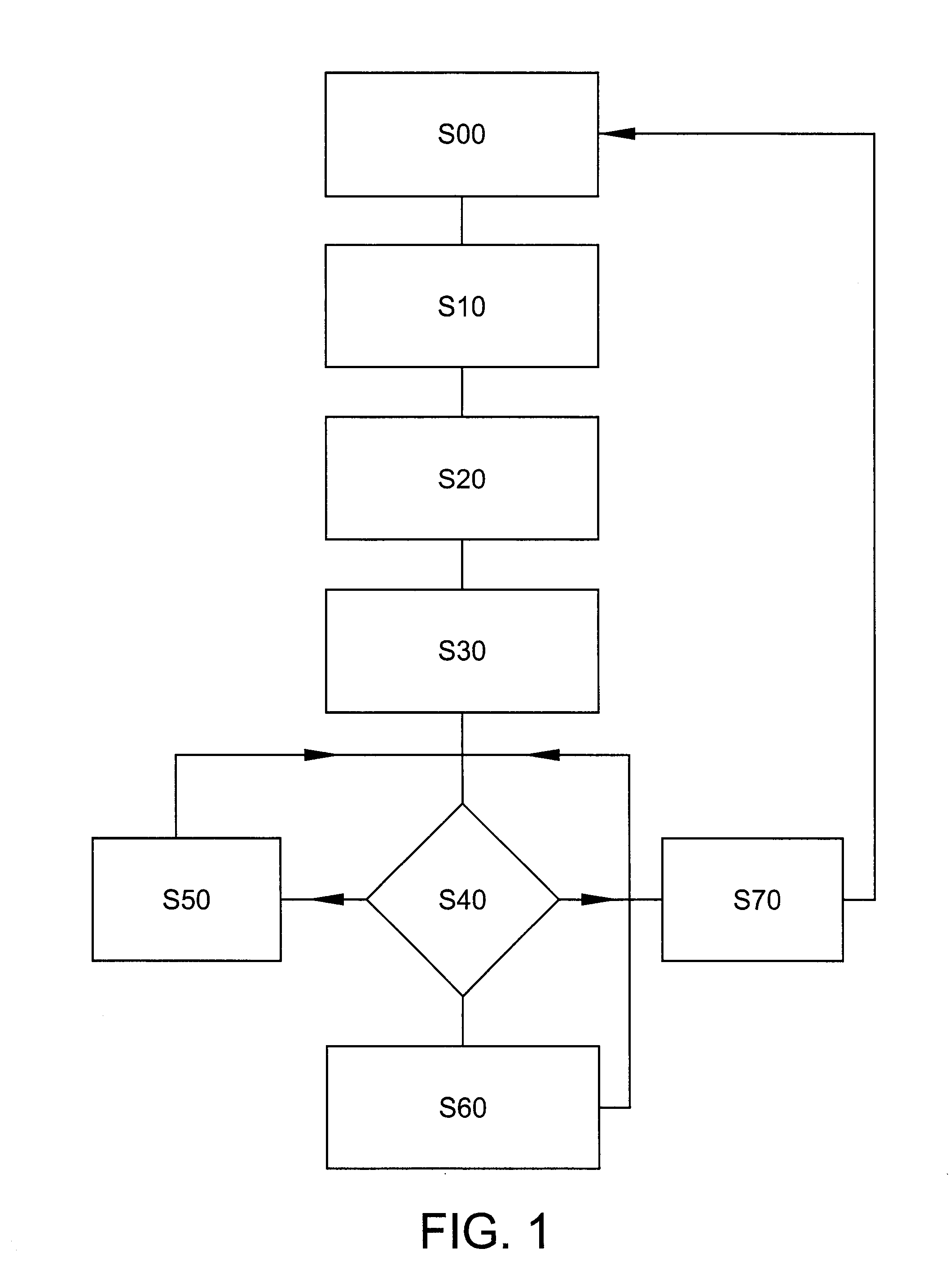
[0026]FIG. 1 shows a schematic flow chart of a method according to an aspect of the invention.

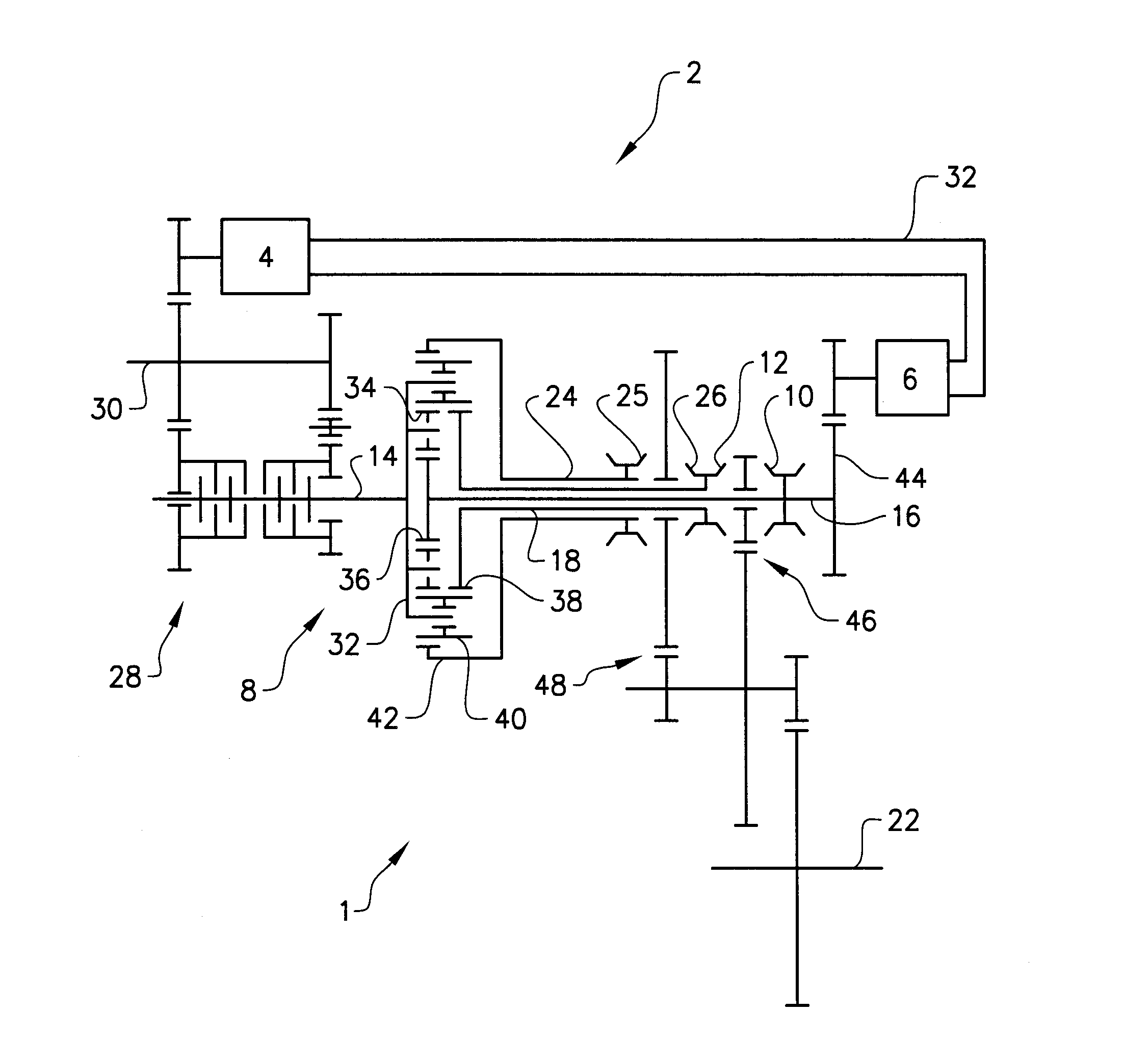
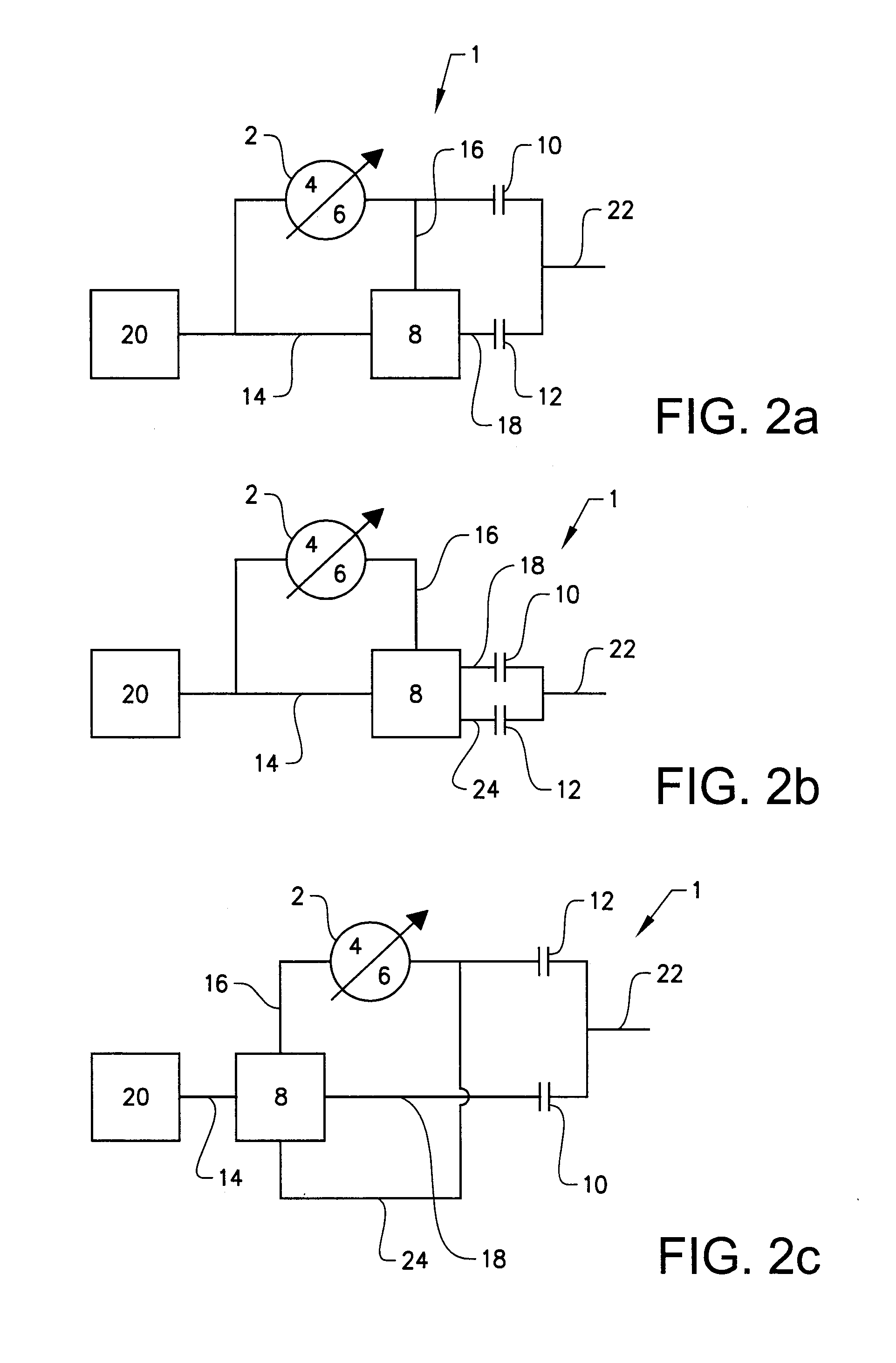
[0027]The method according to an aspect of the invention is used to control a power split continuously variable transmission which includes a variator unit having a first and a second variable displacement hydrostatic machine and a planetary gear unit. The power split continuously variable transmission is operable in at least two different modes. The modes are selected by engaging respective disengaging clutches included in the power split continuously variable transmission. Each mode is associated with a speed ratio range over the power split continuously variable transmission. The speed ratio ranges for pairs of the at least two modes may intersect at operating points where a mode change may take place. At these operating points the power split continuously variable transmission may be engaged in a lock up state. The power split continuously variable transmission has a fixed overall speed...


PUM


Abstract

A power split continuously variable transmission is provided including a variator unit having a first and a second variable displacement hydrostatic machine and a planetary gear unit. The power split continuously variable transmission is arranged to be controlled to perform a simultaneous reduction of displacements of the first and second variable displacement hydrostatic machines during at least a part of a lock up state of the power split continuously variable transmission. A method of operating such a transmission is also provided.

Description

BACKGROUND AND SUMMARY[0001]The invention relates, according to an aspect thereof to a method for controlling a power split continuously variable transmission and a power split continuously variable transmission.[0002]Power split continuously variable transmissions include a mechanical transmission and a variator unit. The mechanical transmission includes a planetary gear unit consisting of one or more planetary gear trains and may also include one or more conventional gear stages. In the mechanical transmission power is transmitted over meshing gear wheels allowing high transmission efficiency at fixed gear ratios. The variator unit has a continuously variable speed ratio. In a power split continuously variable transmission an input power may be split to be distributed over the mechanical transmission and the variator unit to provide a variable overall speed ratio over the continuously variable transmission. The overall speed ratio over the continuously variable transmission is the...

Claims


Application Information

Patent Timeline
IPC IPC(8): F16H47/10F16H61/66F16H61/02
CPCF16H47/10F16H61/0262F16H61/66F04B49/103F16H47/04F16H61/462F16H2200/2023F16H2200/2005F16H2037/0886
Inventor STALBERG, DANIELMATTSSON, PERNORDSTRAND, ANDREAS
Owner VOLVO CONSTR EQUIP
Learn More