Roller clutch assembly

a technology for clutches and roller blinds, applied in the direction of belts/chains/gearrings, mechanical equipment, building components, etc., can solve the problems of not always supporting smooth and light weight operation of clutch mechanisms, and suffer from one serious drawback, so as to achieve smooth raising and lowering of roller blinds

Inactive Publication Date: 2013-10-15
NG PHILIP +1
View PDF2 Cites 13 Cited by
  • Summary
  • Abstract
  • Description
  • Claims
  • Application Information

AI Technical Summary

Problems solved by technology

These sorts of locking roller clutch mechanisms are very popular; however, they suffer from one serious drawback.
When larger or heavier blinds are used in combination with these clutch mechanisms, the locking springs have a tendency to partially seize up, causing the clutch mechanisms to partially lock onto the barrel of the housing and resist the raising and lowering of the blinds.
As a result, these clutch mechanisms do not always support the smooth and light weight operation.

Method used


Image

  • Roller clutch assembly
  • Roller clutch assembly
  • Roller clutch assembly

Examples


Embodiment Construction

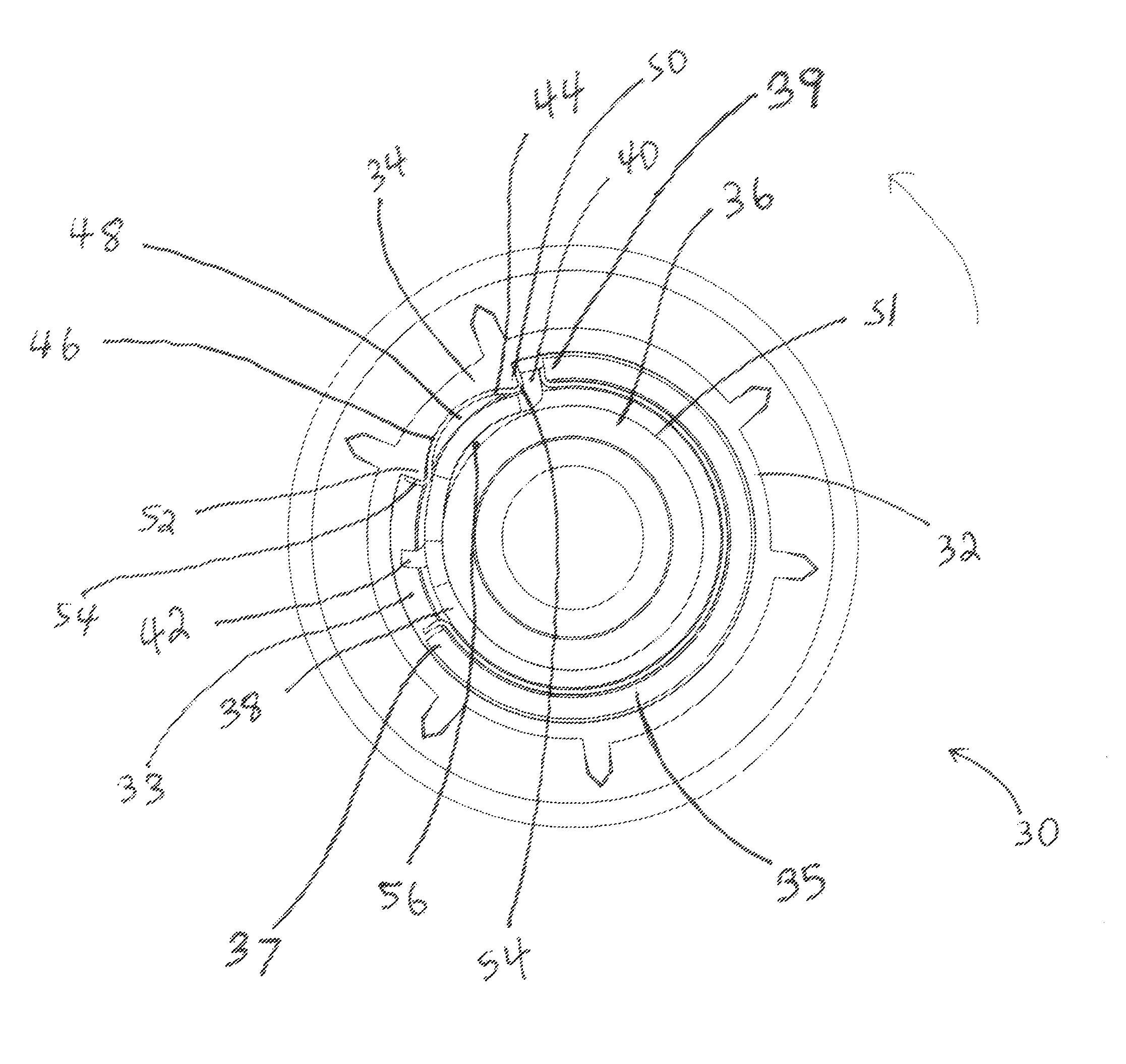
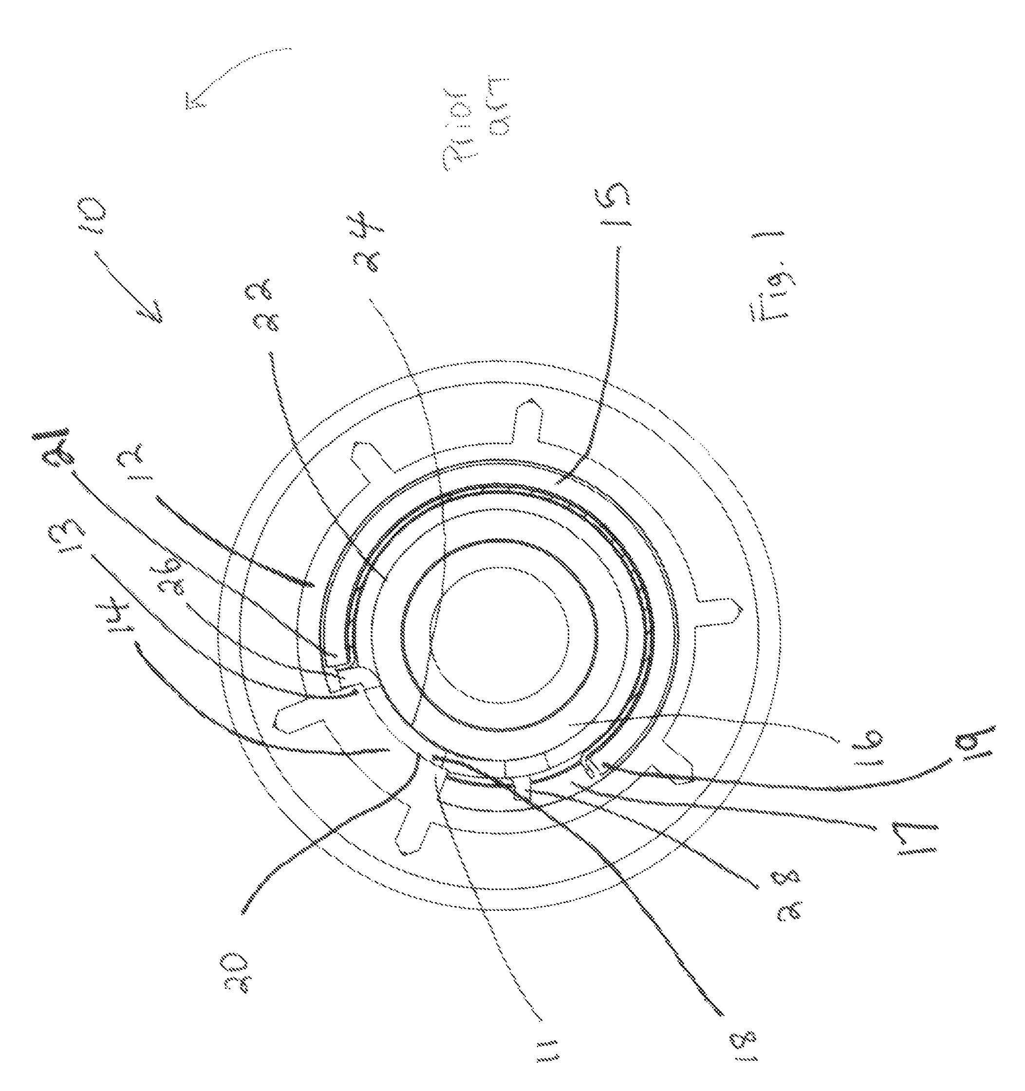
[0012]Referring firstly to FIG. 1, prior art roller clutch assemblies, shown generally as item 10, consist of a barrel 16 mounted within a roller tube mount 12 with a lock spring 18 positioned between them. Lock spring 18 has ends 26 and 28. Roller tube mount 12 has extension 14 which projects towards barrel 16. Extension 14 is dimensioned to fit between ends 26 and 28 and has shoulders 11 and 13 which are configured to engage one of the ends of lock spring 18 when the roller tube mount is rotated relative to barrel 16. When one of the ends of lock spring 18 is engaged from between ends 26 and 28, the spring decreases in diameter causing it to tighten onto barrel 16 and effectively lock the spring to the barrel preventing further movement of the roller tube mount relative to the barrel. This prevents the roller tube mount from accidentally rotating as a result of the weight of the blind (not shown) attached to the roller tube (not shown) which is coaxially mounted to the roller tube...


PUM


Abstract

An improved roller blind clutch assembly is disclosed for controlling the raising and lowering of a roller blind which permits the smooth raising and lowering of roller blinds even if the blinds are heavy. The improved roller blind clutch assembly includes a roller tube mount coaxially and rotatably mounted to a barrel. A clutch member is in turn coaxially and rotatably mounted to the barrel between the roller tube mount and the barrel. The clutch member has a window formed between a first and a second edge of the clutch member. A torsion locking spring is coaxially mounted to the barrel between the barrel and the clutch member. The torsion locking spring has opposite first and second ends which project into the window. The roller tube mount has an extension portion configured to extend into the window and dimensioned to fit between the first and second ends of the torsion locking spring. The extension has opposite first and second shoulders covered by a steel shim configured to fit between the extension and the torsion locking spring. The extension portion is also dimensioned and configured to maintain a gap between the extension and the torsion locking spring; thereby permitting the torsion locking spring from catching on the barrel as the clutch mechanism is used to raise and lower the blind. The extension portion has a concave face with a circular diameter less than the diameter of the torsion locking spring.

Description

CROSS REFERENCE TO RELATED APPLICATION[0001]This application claims priority from U.S. Provisional application Ser. No. 61 / 164,440 filed Mar. 29, 2009, the entirety of which is incorporated herein by reference.FIELD OF THE INVENTION[0002]The invention relates generally to clutch assemblies for roller blinds.BACKGROUND OF THE INVENTION[0003]Roller blinds are generally controlled by a roller clutch assembly which is used to manually raise and lower the blind. These clutch assemblies generally consist of a housing having a barrel portion to which a roller tube support member is rotatably mounted. The blind is coupled to a roller tube which is in turn coupled to the roller tube support member. A clutch member is rotatably mounted to the barrel portion of the housing and is coupled to the roller tube support member. A looped chain is in turn coupled to the clutch member to permit the user to rotate the clutch member (and thereby the roller tube) by pulling on the chain. This permits the ...

Claims


Application Information

Patent Timeline
Patent Type & Authority Patents(United States)
IPC IPC(8): F16D49/04E06B9/56
CPCE06B9/42E06B2009/905
Inventor NG, PHILIPWILLS, NORMAN
Owner NG PHILIP
Why Eureka
Try Eureka