

Robust filtering and prediction using switching models for machine condition monitoring
a switching model and machine condition technology, applied in the field of machine condition monitoring, can solve the problems of complex evolution of sensor signals, imposing a great challenge on the filtering algorithm, and often contaminated sensor signals by nois
Inactive Publication Date: 2013-10-15
SIEMENS CORP
View PDF9 Cites 4 Cited by
- Summary
- Abstract
- Description
- Claims
- Application Information
AI Technical Summary
Problems solved by technology
Sensor signals are often contaminated by noise.
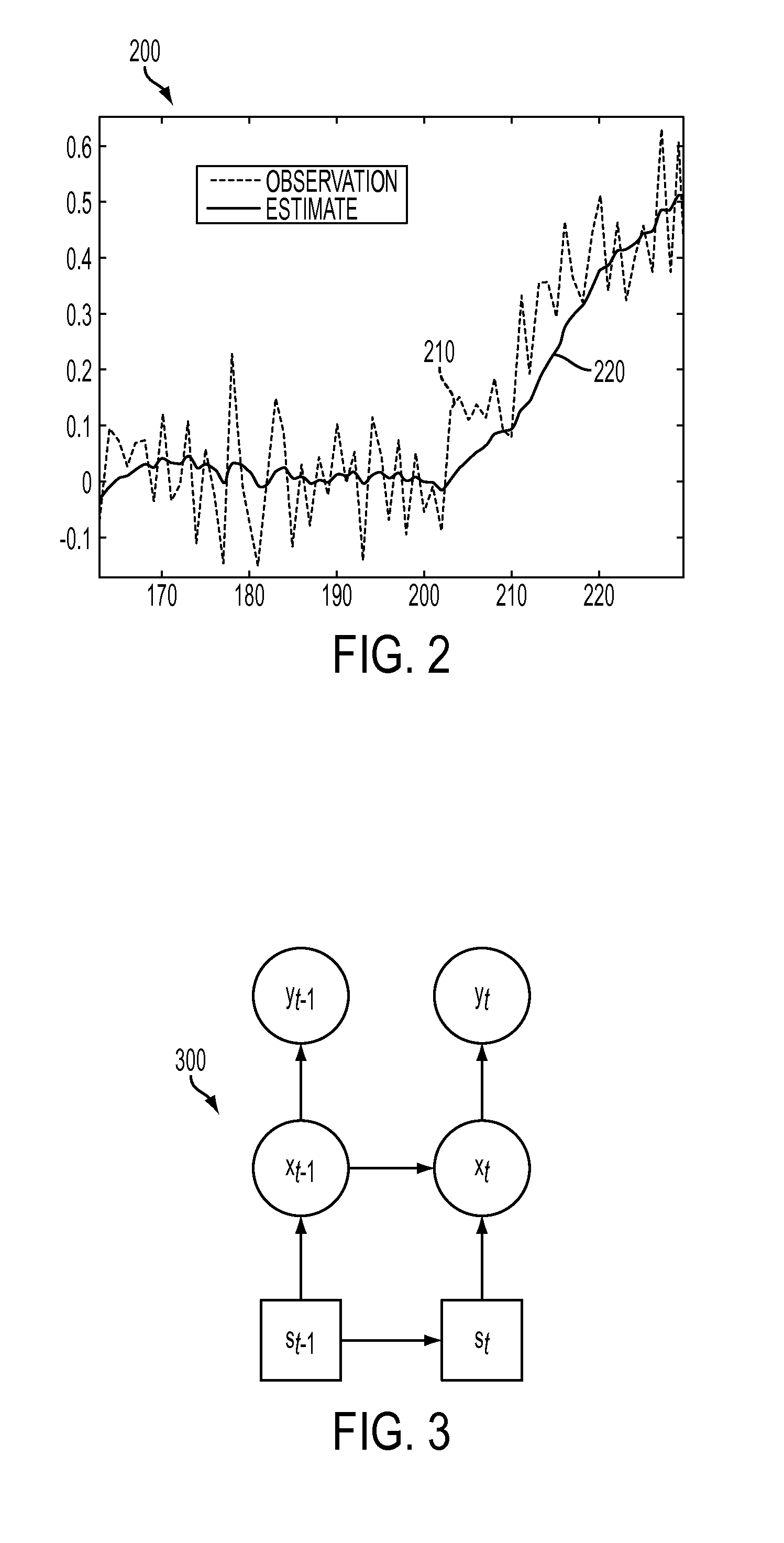
In many real systems, however, the evolution of sensor signals is too complex to be described by a single filtering model.
During spikes such as those at 521, 522, 523 and steps such as steps 511, 512, the true sensor signal changes dramatically in a short period, imposing a great challenge to the filtering algorithm.
Method used
View moreImage
Smart ImageViewing Examples

Examples
Embodiment Construction
is to be understood as being in every respect illustrative and exemplary, but not restrictive, and the scope of the invention disclosed herein is not to be determined from the Description of the Invention, but rather from the claims as interpreted according to the full breadth permitted by the patent laws. It is to be understood that the embodiments shown and described herein are only illustrative of the principles of the present invention and that various modifications may be implemented by those skilled in the art without departing from the scope and spirit of the invention.
Login to View More PUM
 Abstract
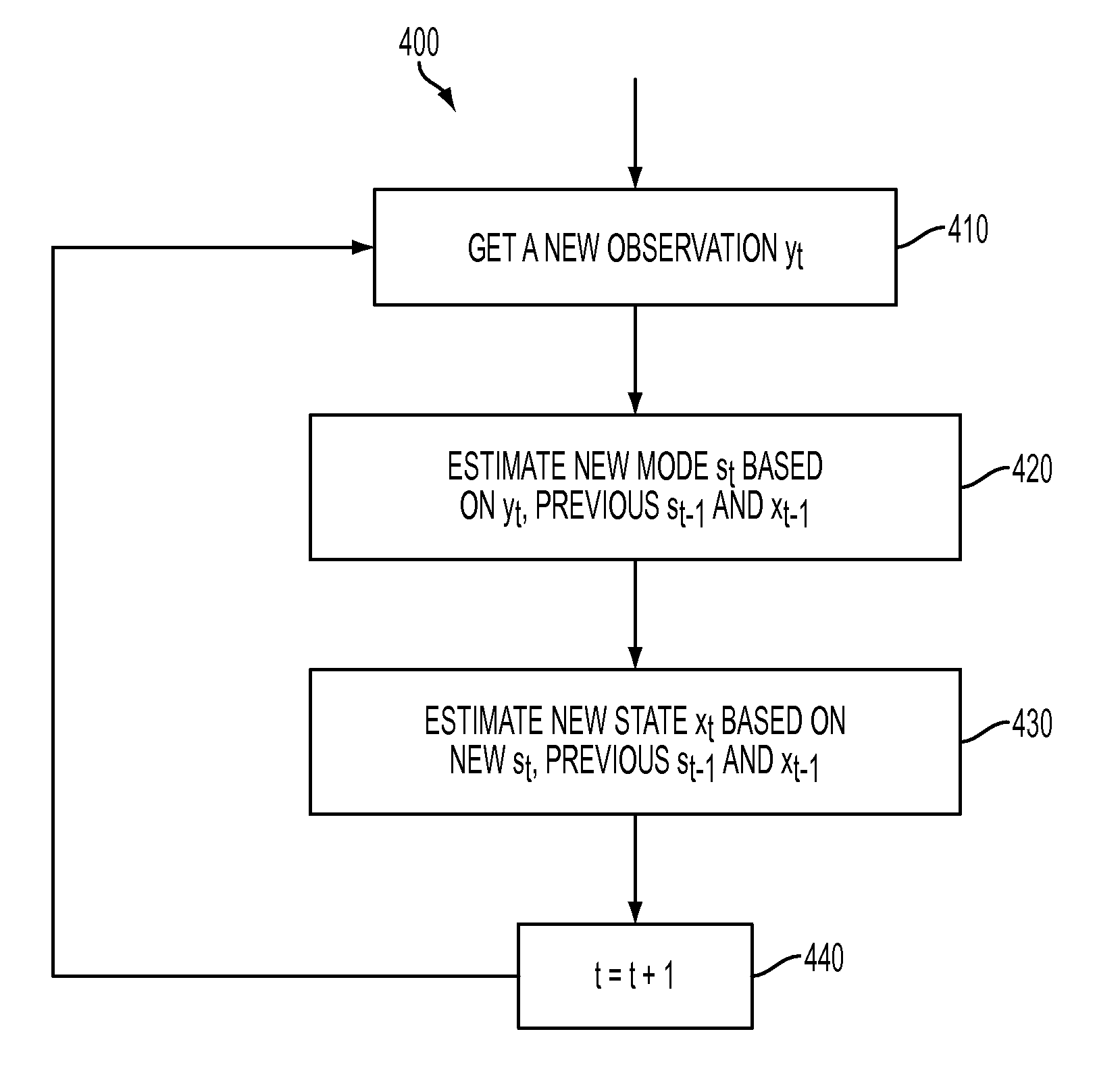
In a machine condition monitoring technique, a sensor reading is filtered using a switching Kalman filter. Kalman filters are created to describe separate modes of the signal, including a steady mode and a non-steady mode. For each new observation of the signal, a new mode is estimated based on the previous mode and state, and a new state is then estimated based on the new mode and the previous mode and state. In the steady mode, evolution covariances of both the observed signal and the rate of change of that signal are low. In the non-steady mode, the evolution covariance of the observed signal is set to a higher value, permitting the observed signal to vary widely, while the evolution covariance of the rate of change of the signal is maintained at a low level.
Description
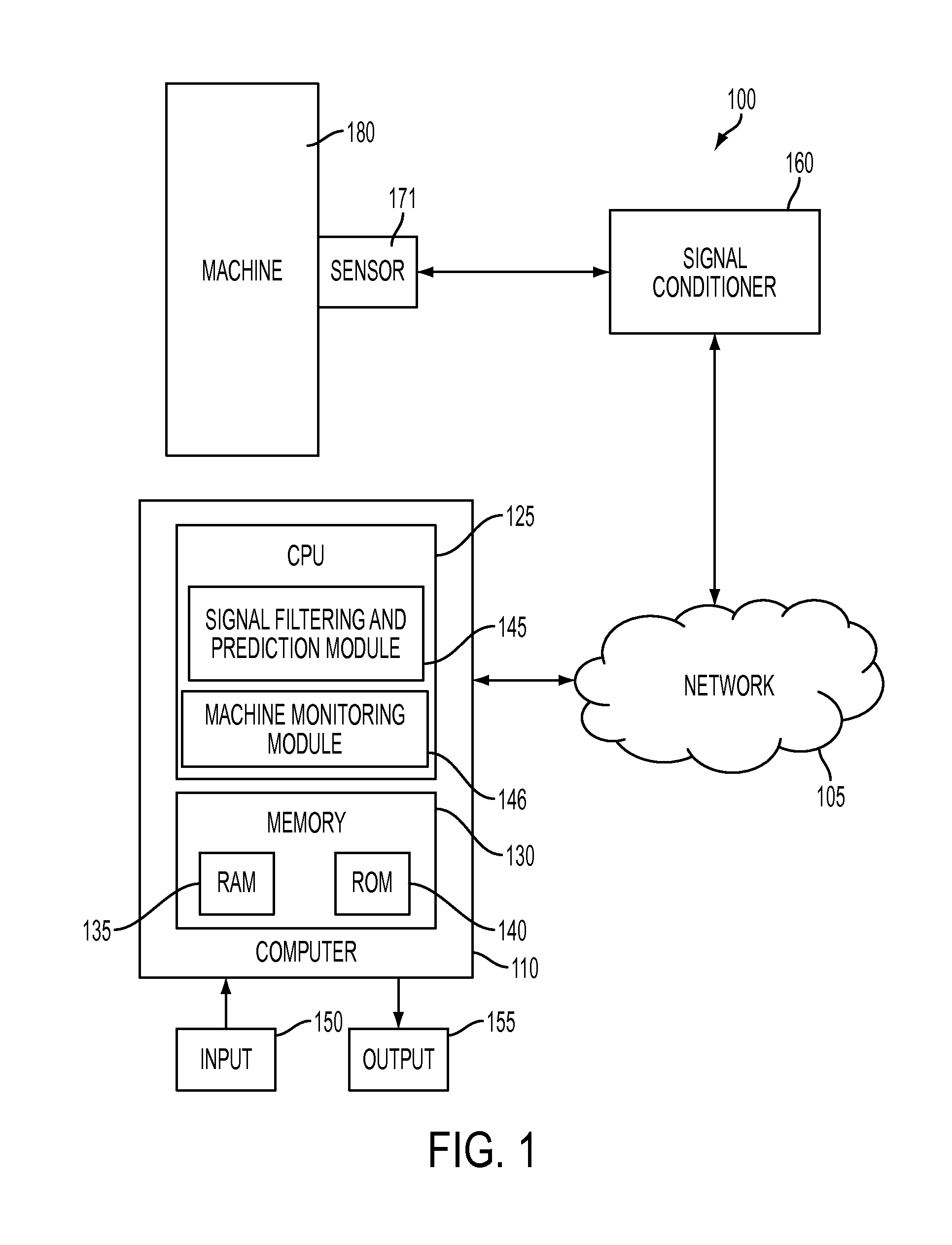
CLAIM OF PRIORITY[0001]This application claims priority to, and incorporates by reference herein in its entirety, pending U.S. Provisional Patent Application Ser. No. 61 / 106,701, filed Oct. 20, 2008, and entitled “Robust Filtering and Prediction Using Switching Models for Machine Condition Monitoring.”FIELD OF THE DISCLOSURE[0002]The present invention relates generally to machine condition monitoring for the purpose of factory automation. More specifically, the invention relates to techniques for filtering observed values in order to estimate a true signal value without noise.BACKGROUND[0003]The task of machine condition monitoring is to detect faults as early as possible to avoid further damage to a machine. That is usually done by analyzing data from a set of sensors, installed on different parts of a machine, for measuring temperature, pressure, vibrations, etc. When a machine works normally, the sensor data is located within a normal operating region. When the sensor data deviat...
Claims
Login to View More Application Information
Patent Timeline
 Patent Type & AuthorityPatents(United States)
IPC IPC(8): G06F15/00
CPCG05B23/0221
InventorYUAN, CHAO
OwnerSIEMENS CORP