
Sensor fusion for model-based detection in pipe and cable locator systems

a technology of sensor fusion and model-based detection, which is applied in the field of sensor fusion for model-based detection in pipe and cable locator systems, can solve the problems of difficult interpretation of the typically graphical output of such systems, complex interpretation, and limited use of gpr, and achieve the effect of improving the position estimation of targeted hidden conductors

Active Publication Date: 2010-11-16
BUSAN TRANSPORTATION CORPORATION
View PDF55 Cites 99 Cited by
  • Summary
  • Abstract
  • Description
  • Claims
  • Application Information

AI Technical Summary

Benefits of technology

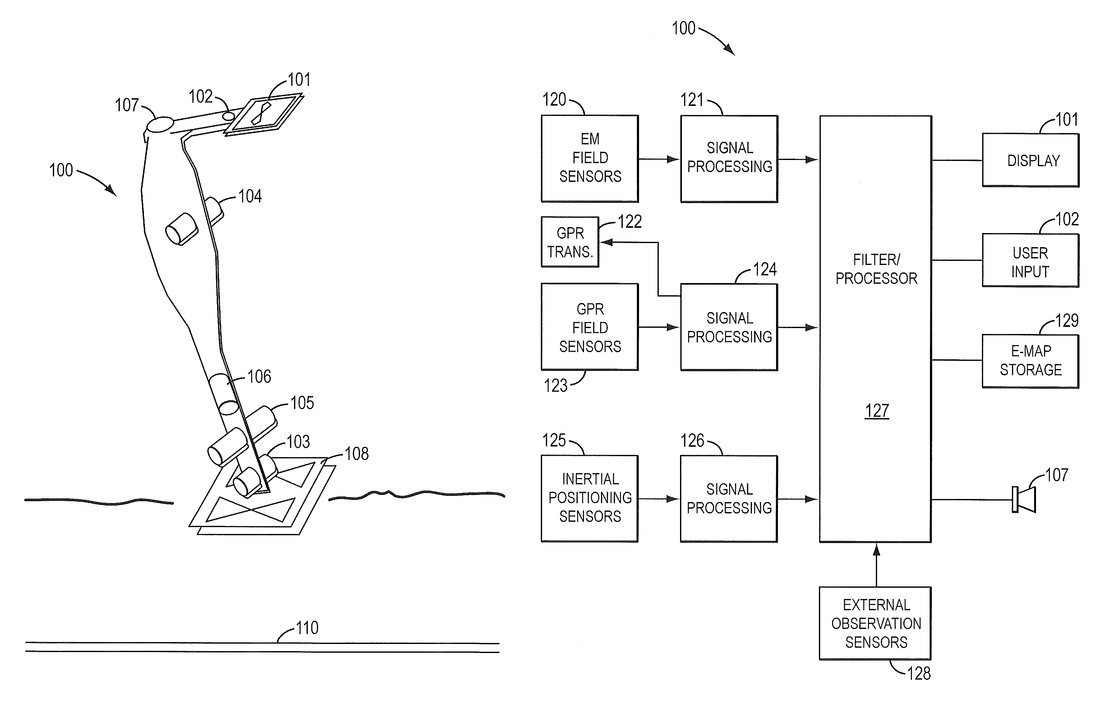
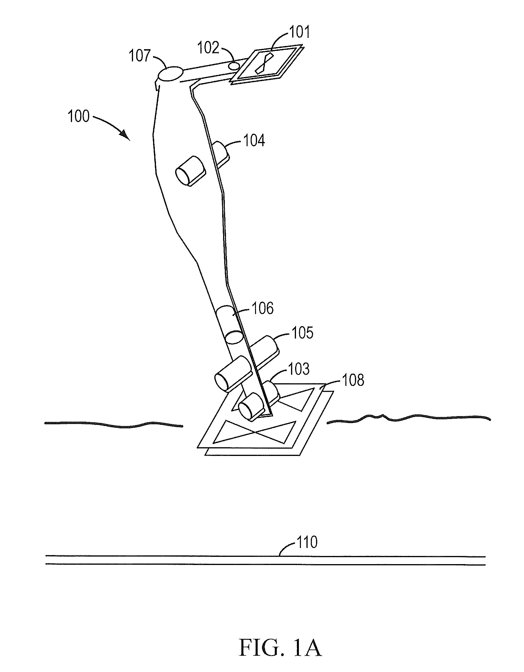
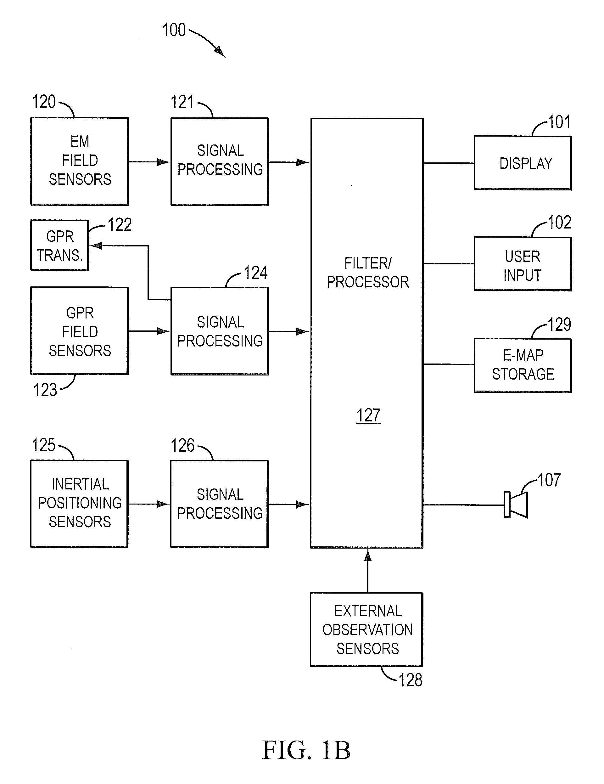
"The present invention is a combined system that uses inertial, electromagnetic, and radar sensors to locate underground lines and pipes. The system fuses signals from these sensors to provide accurate positioning of the underground line. The system can simultaneously locate both conductive and non-conductive cables and pipes. The system includes a filter that fuses signals from field sensors and inertial position sensors, treating them as loosely or tightly coupled sensors. The system can also store position and field values to create an electronic map of the underground line. The method involves measuring field and inertial navigation values, fusing them with external position parameters, and using a Kalman filter to update the state vector. The system and method provide improved accuracy and efficiency in locating underground lines and pipes."

Problems solved by technology

However, the widespread use of GPR has (in part) been limited by the difficulties in interpretation of the typically graphical output of such systems, which are much more complex than EM locators.
In some cases, there may be bias in the targeted conductor's estimated centerline as a result of distortion due to bleedover.
A disadvantage with relying solely on an EM line locator device for determining the location and depth of a target conductor is that the locator may fail to identify and distinguish among various utility conduits and conductors.
EM line locator devices especially may fail to locate non-conductive lines, such as, for example, gas lines, fiber optic lines and plastic water lines when those lines are not marked with trace wires.
However, such systems present to the user a fairly complex grey-scale or color image of the radar pulse echo amplitude in a 2-D map of depth vs. horizontal ground position.
This type of display is useful in survey and mapping applications, but provides far too much information for the ordinary user trained in line location techniques.
In conventional GPR systems, the results that signify the presence of underground utility lines are often not available until after post processing of the image data collected on an external computer.
Conventional GPR systems focus on collection of data, and not the detection and tracking in real-time of an individual utility line and therefore provide highly complex displays of that data.
Further, features presented in the images are often inconsistent and unrecognizable when these maps are presented in real-time to the user.
Using conventional methods without off-line image processing, centerline errors of a few centimeters are attainable with EM line locators but are not achievable with a GPR line locator.
Determining the dielectric constant of the soil is often difficult at best, resulting in depth determinations that are subject to 20% tolerances in this scenario.
Unfortunately, markings are not permanent and therefore can not be relied on for future locates at the same site.

Method used


Image

  • Sensor fusion for model-based detection in pipe and cable locator systems
  • Sensor fusion for model-based detection in pipe and cable locator systems
  • Sensor fusion for model-based detection in pipe and cable locator systems

Examples


Embodiment Construction

[0041]Various methods have been employed on EM locators to ensure that the results presented to the user (depth, centerline, and AC current) associated with the target conductor are accurate. The traditional rule of thumb is that the peak field measurement of the center of the line, determined by detectors arranged to measure horizontal fields, and the null field measurement of the center of the line, determined by detectors arranged to measure vertical fields, should not differ by more than a couple of centimeters or so. If those measurements differ by more than this threshold, the field is distorted and the predicted centerline could be in error. U.S. Pat. No. 6,815,953, (the '953 patent) by Russell N. Bigelow, and assigned to Metrotech Corporation, which is herein incorporated by reference in its entirety, discloses a method of comparing three point measurements in space and determining an error function based on how well the measured magnetic field conforms to the assumed model....


PUM


Abstract

Line locator systems that fuse traditional sensors used in a combined pipe and cable locator (electromagnetic coils, magnetometers, and ground penetrating radar antennas) with low cost inertial sensors (accelerometers, gyroscopes) in a model-based approach are presented. Such systems can utilize inexpensive MEMS sensors for inertial navigation. A pseudo-inertial frame is defined that uses the centerline of the tracked utility, or an aboveground fixed object as the navigational reference. An inertial sensor correction mechanism that limits the tracking errors over time when the model is implemented in state-space form using, for example, the Extended Kalman Filter (EKF) is disclosed.

Description

[0001]This disclosure is a continuation-in-part of U.S. patent application Ser. No. 10 / 997,729 filed Nov. 23, 2004, now U.S. Pat. No. 7,113,124 “Centerline and Depth Locating Method for Non-Metallic Buried Utility Lines”. which claims priority to U.S. Provisional App. No. 60 / 525,291 filed on Nov. 25, 2003, by James W. Waite, each of which is herein incorporated by reference in its entirety. This disclosure further claims priority to U.S. Provisional App. No. 60 / 592,835 filed on Jul. 29, 2004, by James W. Waite, which is also herein incorporated by reference in its entirety.BACKGROUND[0002]1. Field of the Invention[0003]The present invention relates to the enhancement of traditional cable location methods by a fusion of electromagnetic sensors and / or ground penetrating radar sensors with inertial sensors in a state-space framework.[0004]2. Discussion of Related Art[0005]Underground pipe and cable locators (sometimes termed line locators) based on electromagnetic (EM) methods have exi...

Claims


Application Information

Patent Timeline
Patent Type & Authority Patents(United States)
IPC IPC(8): G01S13/89G01V11/00G01S19/48
CPCG01S13/86G01V11/00G01S13/885
Inventor WAITE, JAMES W.WELARATNA, RUWAN
Owner BUSAN TRANSPORTATION CORPORATION
Learn More