Method for fabricating a multi-density polymeric interbody spacer

a multi-density polymer and interbody technology, applied in the field of synthetic bone polymer implants, can solve the problems of increased cost and product backorder, disadvantageous autograft procedures, undesirable spinal fusion applications, etc., and achieve the effects of promoting bone fusion, restoring height, and increasing the strength of the interbody spacer

Inactive Publication Date: 2011-01-20
DOCTORS RES GROUP
View PDF28 Cites 59 Cited by
  • Summary
  • Abstract
  • Description
  • Claims
  • Application Information

AI Technical Summary

Benefits of technology

[0010]According to the present invention, a multi-density polymeric interbody spacer is a synthetic spacer that may be implanted to restore height and promote bone fusion after discectomy or corpectomy. The multi-density polymeric interbody spacer is formed from biocompatible polymeric foam for osteoconductivity, preferably a polyurethane-urea. The multi-density structure provides for combined strength and porosity. The multi-density spacer includes direct adhesion and mechanical interlocking between different density regions to increase the strength of the interbody spacer. The multi-density spacer may also include geometric surface features to enhance positioning and fit of the spacer.

Problems solved by technology

However, autograft procedures are disadvantageous since they require a second operative site with associated pain.
However, machined allograft interbody spacers have other drawbacks that make them undesirable for spinal fusion applications.
For example, there is a limited supply of qualified bone that can be formed into machined allograft interbody spacers, which results in increased cost and product backorder.
Also, the size and shape of available qualified bone limits the size of machined allograft spacers.
Additionally, to be qualified, the transplanted bone must be tested for disease and undergo expensive sterilization to reduce the risk of disease transmission.
However, even with testing and sterilization, the risk of disease transmission cannot be completely eliminated.
The cadaver bone must also be manufactured into the proper spacer geometry for the machined allograft interbody spacer since the transplanted cadaver bone cannot exactly match the disk being removed from a patient.
The varied quality of source bone also makes it challenging to maintain uniform mechanical properties of allograft interbody spacers.
However, a cadaver will likely only produce a few such spacers since there are a very limited number of bone sources to produce a sufficient geometry of sufficient cortical and cancellous bone.
Thus, allograft interbody spacers are typically assembled from multiple bone density regions, which requires the additional manufacturing of a mechanical interlock, such as a pin feature or a dovetail feature, between the parts of the multipart spacer, thereby increasing cost of manufacturing.
These hollow rigid spacers have many deficiencies.
For example, metal spacers are too stiff to share the load across the vertebrae and PEEK is very brittle.
Rigid spacers formed from metal or PEEK also fail to provide a structure for osteoconduction.
Additionally, hollow rigid spacers may result in vertebrae getting crushed due to their stiffness.
Hollow rigid spacers formed from metal also require a relatively significant amount of machining, increasing manufacturing complexity.
These have the same disadvantage of hollow rigid structures formed of metal in that they are too stiff to share the load.
However, while the porous polyurethane structure is ideal for osteoconduction, polyurethane interbody spacers formed with a porous structure lack the strength to withstand the forces seen after spinal fusion.

Method used


Image

  • Method for fabricating a multi-density polymeric interbody spacer
  • Method for fabricating a multi-density polymeric interbody spacer
  • Method for fabricating a multi-density polymeric interbody spacer

Examples


Embodiment Construction

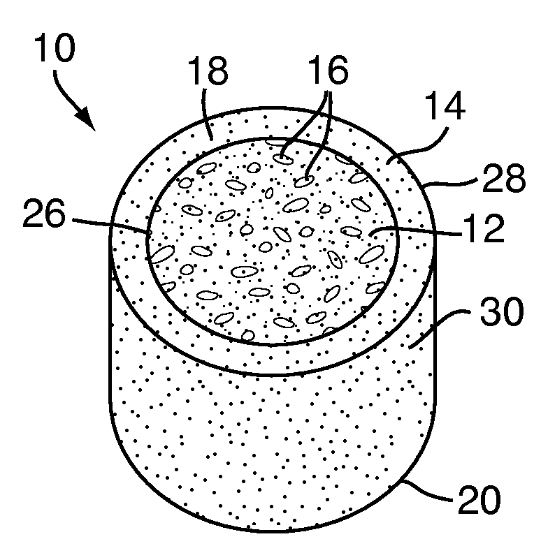
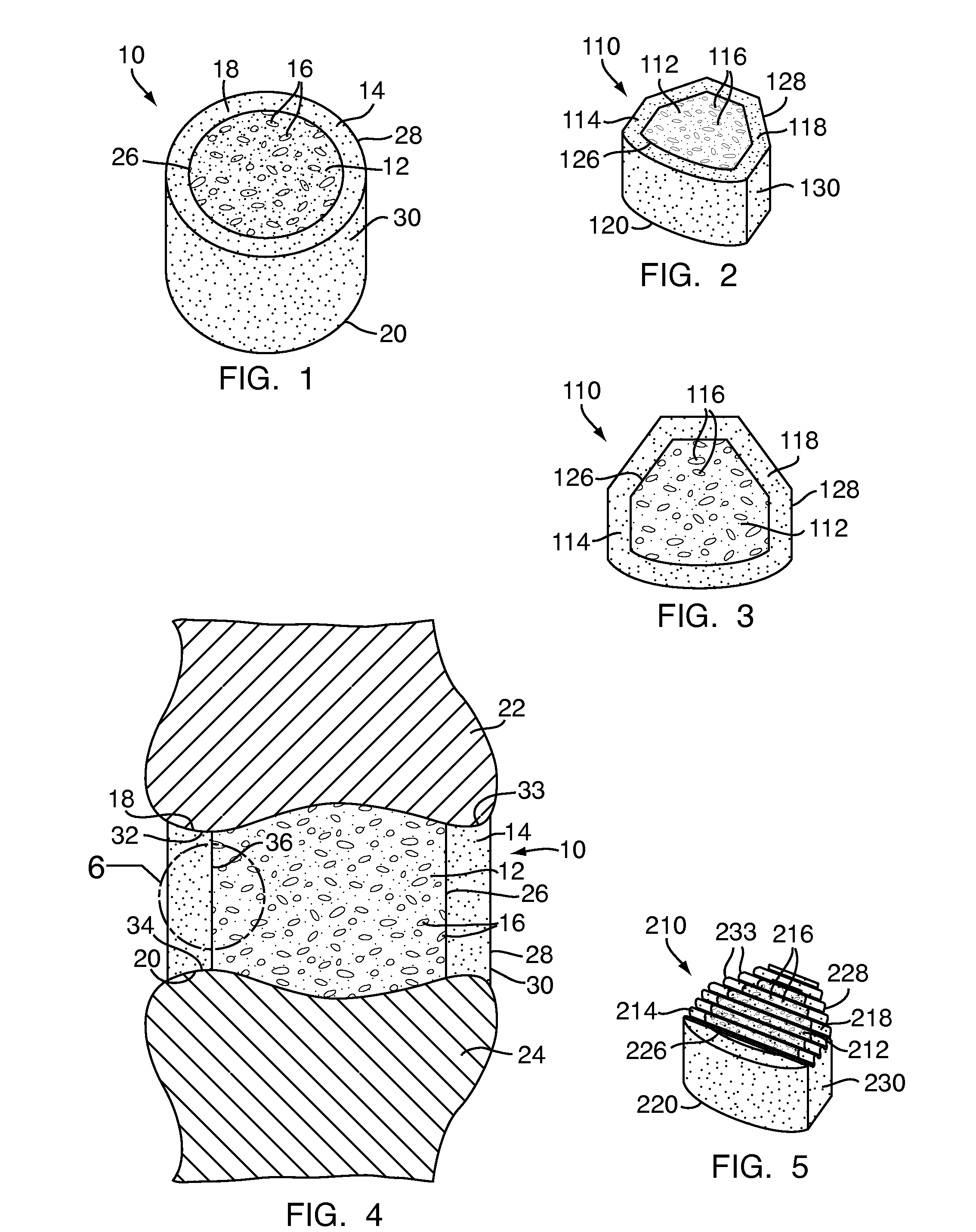
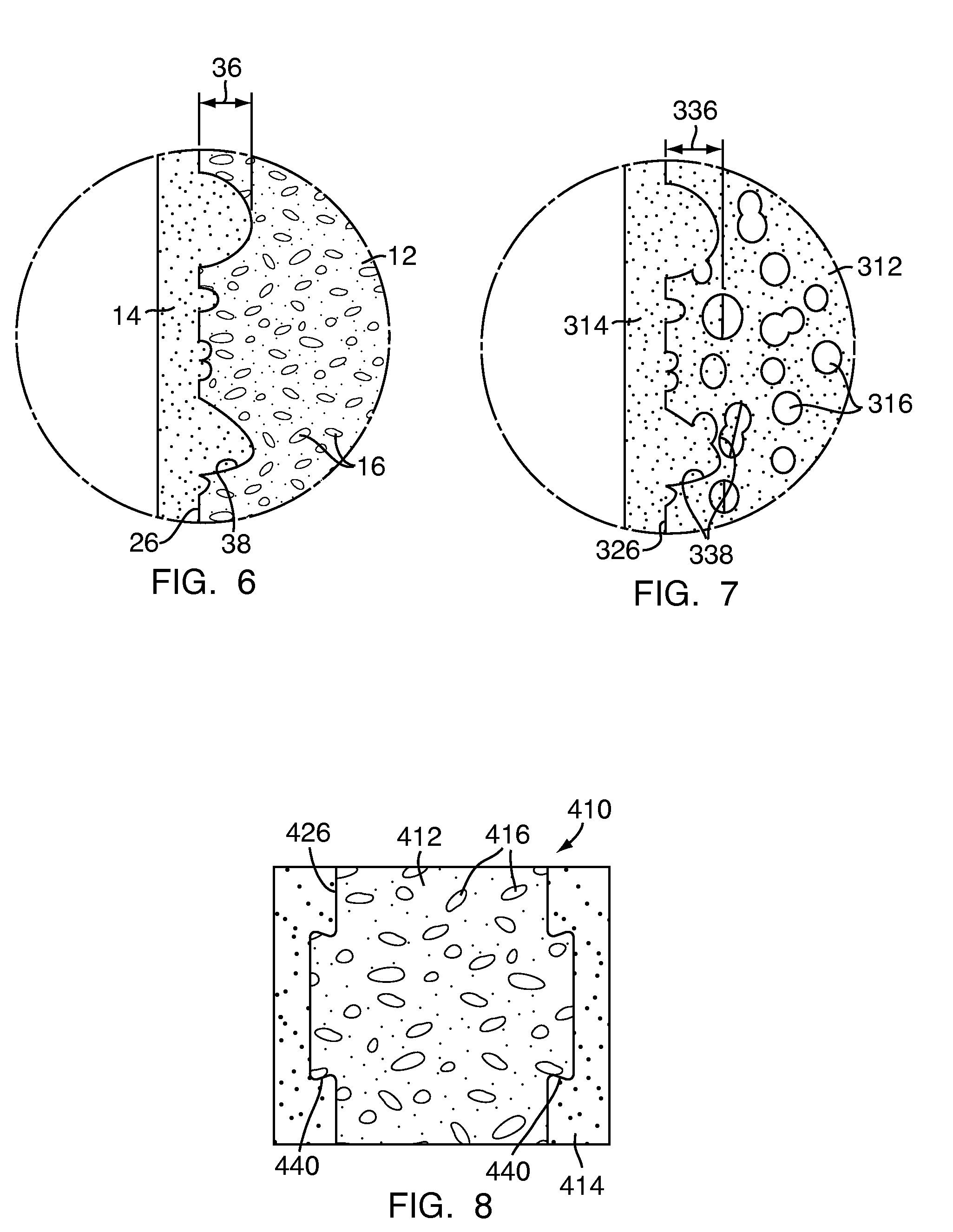
[0048]Referring to FIG. 1, a multi-density polymeric interbody spacer 10, for replacing an intervertebral disc in spinal fusion surgery to restore height and promote bone fusion, includes a first density region 12 forming a central core and a second density region 14 surrounding the first density region 12. The first density region 12 and the second density region 14 are formed from a biocompatible polymeric foam material, which is discussed below in greater detail. The first density region 12 is formed to have a low density and a high porosity, providing a porous structure with pores 16 to allow bony ingrowth or osteoconduction after implantation of the multi-density polymeric interbody spacer 10 during spinal fusion surgery. The second density region 14 has a relative high density with low porosity to provide the multi-density polymeric interbody spacer 10 with strength to withstand spinal fusion forces, which, for example, may be in the vicinity of two thousand Newtons (2000 N) f...


PUM

PropertyMeasurementUnit
pressureaaaaaaaaaa
porosityaaaaaaaaaa
porosityaaaaaaaaaa

Abstract

A multi-density polymeric interbody spacer formed from biocompatible material for osteoconductivity includes multiple density regions of different porosity to provide both strength and osteoconductivity. An interface region is formed between the density regions to provide both direct adhesion and mechanical interlocking between the different density regions to increase the strength of the multi-density polymeric interbody spacer. A method for forming the multi-density polymeric interbody spacer includes curing a first density region to achieve a first target porosity. A second density region may then be molded to the first density region to achieve a second target porosity. A portion of the second density region partially flows into pores of the first density region, providing direct adhesion and mechanical interlocking between the first and second density regions.

Description

FIELD OF THE INVENTION[0001]The present invention relates to implants for use in interbody fusion and methods of manufacturing such implants and, more particularly, to implants formed from synthetic bone polymers.BACKGROUND OF THE INVENTION[0002]There are many situations in which bones or bone fragments are fused, including fractures, joint degeneration, abnormal bone growth, infection and the like. For example, circumstances requiring spinal fusion include degenerative disc disease, spinal disc herniation, discogenic pain, spinal tumors, vertebral fractures, scoliosis, kyphosis, spondylolisthesis, spondylosis, Posterior Rami Syndrome, other degenerative spinal diseases, and other conditions that result in instability of the spine.[0003]During spinal surgical procedures, a discectomy or corpectomy may be performed to remove an intervertebral disc or a vertebral body or portion thereof. It is known to implant interbody spacers to replace the removed intervertebral disc or vertebral b...

Claims


Application Information

Patent Timeline
Patent Type & Authority Applications(United States)
IPC IPC(8): B29C67/20
CPCA61B5/064B29C44/3403A61B2019/5445A61B2019/5483A61B2019/5487A61B2019/5491A61B2019/5495A61F2/442A61F2/4465A61F2/447A61F9/0136A61F2002/30006A61F2002/30011A61F2002/30056A61F2002/3008A61F2002/30448A61F2002/30594A61F2002/30617A61F2002/30619A61F2002/30772A61F2002/30774A61F2002/30795A61F2002/30797A61F2002/30904A61F2002/3093A61F2002/30957A61F2002/30971A61F2002/3266A61F2002/4629A61F2220/005A61F2250/0015A61F2250/0023A61F2250/0032A61F2250/0096A61F2250/0097A61F2250/0098A61F2310/00017A61F2310/00023B29C44/04B29C44/1214A61B19/54A61B2090/3983A61B2090/3945A61B2090/3991A61B2090/3995A61B90/39A61B2090/3987A61F2002/3241
Inventor DESLAURIERS, RICHARD J.JANNETTY, JOSEPHKOLB, ERICTOMICH, JOHN A.AKKARAPAKA, NARESH
Owner DOCTORS RES GROUP
Why Eureka
Try Eureka