3D printing tantalum rod

A 3D printing and threaded part technology, applied in the field of 3D printing tantalum rods, can solve problems such as uneven distribution of pore structure, poor bone conduction and bone fusion performance, and treatment failure, so as to avoid unsatisfactory bone ingrowth, avoid surgical revision, The effect of promoting bone conduction

Inactive Publication Date: 2020-06-30
BEIJING CHUNLIZHENGDA MEDICAL INSTR
View PDF2 Cites 1 Cited by
  • Summary
  • Abstract
  • Description
  • Claims
  • Application Information

AI Technical Summary

Problems solved by technology

However, during the implantation process of the tantalum rod, the tantalum rod needs to bear a large force, and the tantalum rod will be twisted or broken when the bone is finally filled.
At the same time, during the use of the tantalum rod in the prior art, the size of the drilled hole is required to be consistent with the size of the tantalum rod. In the actual operation process, the diameter and depth of the drilled hole are larger than the tantalum rod, which will cause The top of the tantalum rod cannot be in contact with the bottom of the drilled hole. After the tantalum rod is implanted, it cannot play an osteoinductive effect, resulting in failure of the treatment.
[0003] Due to the limitations of the preparation and processing technology, the current porous tantalum implant has a single channel, uneven pore structure, and uncontrollable; the distribution of the pore structure is not uniform, and the connectivity of the channel is poor, which leads to the matching of the mechanical properties of the porous tantalum implant with the human bone. Poor, poor bone conduction and bone fusion performance, which limits its application and performance in the field of orthopedics
The tantalum rod has a slight retreat after implantation, which affects the postoperative recovery effect and causes troublesome revision

Method used


Image

  • 3D printing tantalum rod
  • 3D printing tantalum rod
  • 3D printing tantalum rod

Examples


Embodiment Construction

[0023] In order to enable those skilled in the art to better understand the technical solution of the present invention, a 3D printing tantalum rod of the present invention will be further described in detail below in conjunction with the drawings and specific embodiments.

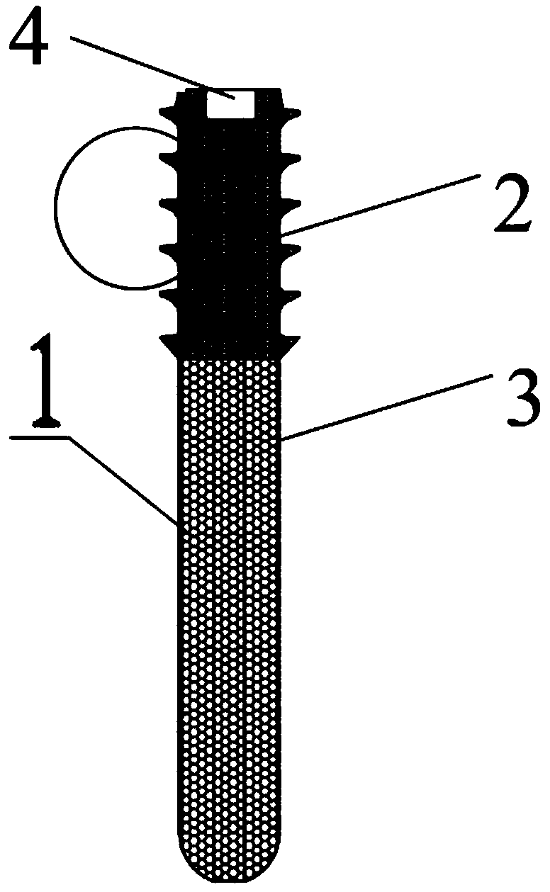
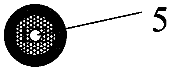
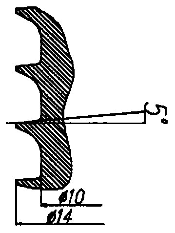
[0024] Such as Figure 1-3 As shown, the tantalum rod 1 includes a threaded portion 2 and a multi-stage hole portion 3, wherein the threaded portion 2 and the multi-stage hole portion 3 are provided with a through hole 5 that penetrates up and down, and the diameter of the through hole is φ3mm. The setting of the through hole Conducive to continuous decompression during and after surgery, the installation of the tantalum rod can be screwed in and positioned along the positioning pin through the through hole; moreover, after the tantalum rod is screwed in, the guide pin can be easily taken out from the through hole; A well-filled bone tissue can also be injected through the through hole through the feeder, ...


PUM

PropertyMeasurementUnit
diameteraaaaaaaaaa
distanceaaaaaaaaaa
diameteraaaaaaaaaa

Abstract

The invention provides a 3D printing tantalum rod. The tantalum rod includes a threaded part and a multi-level hole part, wherein the threaded part and the multi-level hole part are provided with a through hole penetrating up and down, and the surfaces of the threaded part and the multi-level hole part are both provided with circular holes. The tantalum rod can promote bone conduction and bone fusion, the pore structure can be adjusted, and the mechanical properties such as elastic modulus can be adjusted and are closer to the performance of human bones without stress shielding problems. The tantalum rod is provided with the through hole, so that accurate positioning during operation is facilitated; through the through hole, a related substance is conveniently taken out and injected to achieve the effect of continuous decompression; and the threaded part of the tantalum rod has a 5 degree self-locking anti-rotation thread structure, so that previous unsatisfactory bone growth due to fretting and surgical revision are avoided.

Description

technical field [0001] The invention relates to a human body implant material, in particular to a 3D printed tantalum rod. Background technique [0002] For example, the prior art CN109806032A discloses a porous tantalum rod and its preparation method, which discloses that the tantalum rod is prepared by a 3D printing process, and the tantalum rod is porous and consists of a threaded part and a multi-level hole. However, during the implantation process of the tantalum rod, the tantalum rod needs to bear a large force, and the tantalum rod will be twisted or broken when the bone is finally filled. At the same time, during the use of the tantalum rod in the prior art, the size of the drilled hole is required to be consistent with the size of the tantalum rod. In the actual operation process, the diameter and depth of the drilled hole are larger than the tantalum rod, which will cause The top of the tantalum rod cannot be in contact with the bottom of the drilled hole, and aft...

Claims


Application Information

Patent Timeline
Patent Type & Authority Applications(China)
IPC IPC(8): A61L27/56A61L27/04A61L27/50B22F3/11B33Y80/00B33Y10/00A61F2/28A61F2/30
CPCA61F2/28A61F2/2846A61F2/30A61F2/30771A61F2002/2835A61F2002/30199A61F2002/30476A61F2002/30772A61F2002/3085A61F2002/3093A61F2002/30985A61L27/047A61L27/50A61L27/56A61L2430/02B22F3/11B33Y10/00B33Y80/00
Inventor 史春宝许奎雪史文超李明洋王振国
Owner BEIJING CHUNLIZHENGDA MEDICAL INSTR
Why Eureka
Try Eureka