Method and apparatus for treating a vertebral body

Inactive Publication Date: 2011-04-26
SPINEOLOGY
View PDF436 Cites 129 Cited by
  • Summary
  • Abstract
  • Description
  • Claims
  • Application Information

AI Technical Summary

Benefits of technology

[0011]In one embodiment of the method, the bone filler is injected until the cavity is completely filled stabilizing the vertebral body. In another embodiment of the metho

Problems solved by technology

However there are many disease states and aging processes that impact the patient.
Osteoporosis and metastatic disease reduce the structural integrity of the vertebral bodies, predisposing them to fracture.
Vertebral fractures can lead to loss of vertebral height which can exacerbate existing neurological condition or it can predispose the spine to other symptoms.
Back pain often results from these conditions.
Generally, fractures an

Method used


Image

  • Method and apparatus for treating a vertebral body
  • Method and apparatus for treating a vertebral body
  • Method and apparatus for treating a vertebral body

Examples


Example

[0042]The various container devices and the methods for using the container devices are disclosed in the context of the treatment of vertebral bodies. It should be recognized that the inventions may be used in other bones which present the same or similar pathologies, including but not limited to tibial plateaus, distal radius fractures, calcaneous fractures.

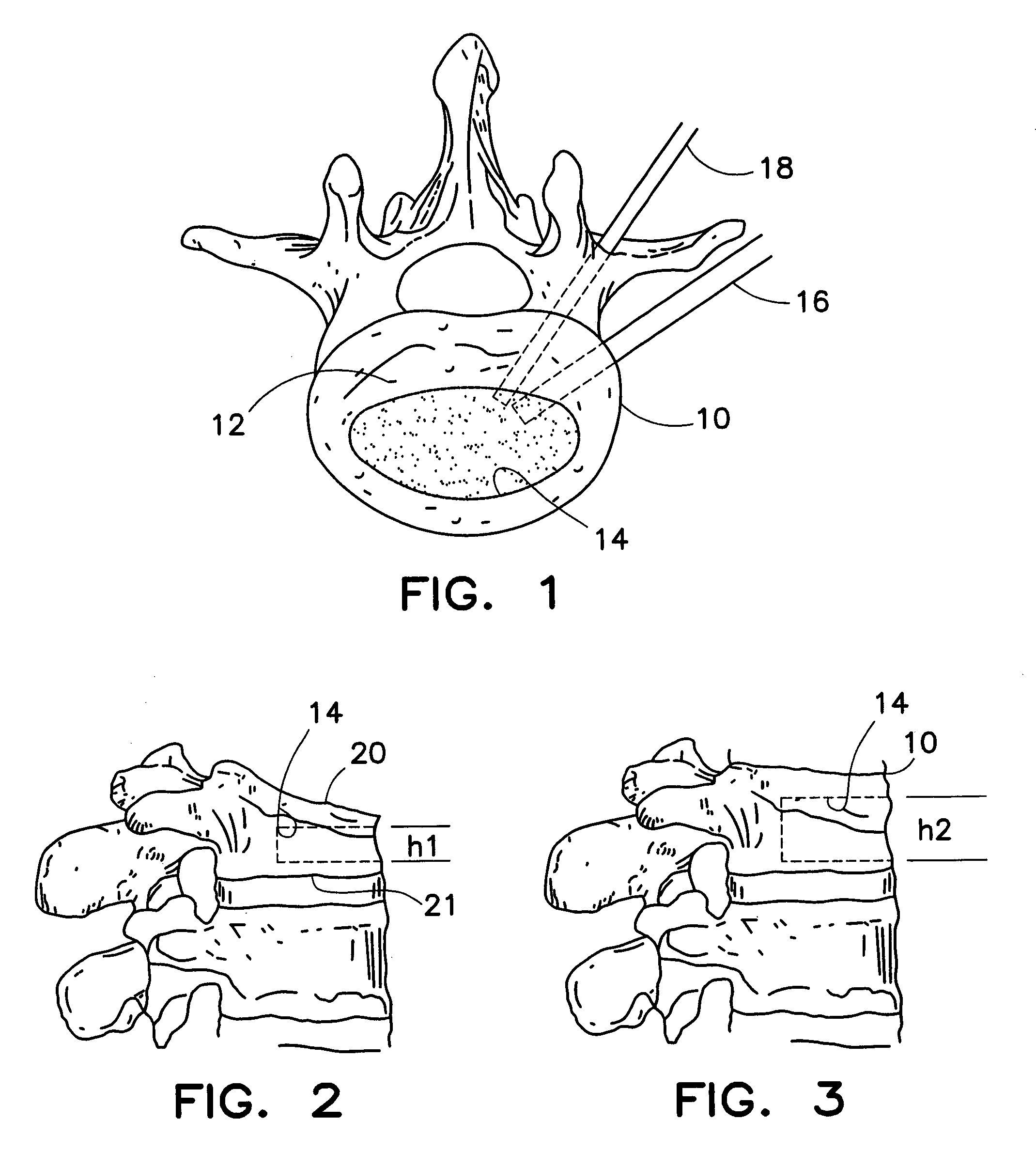
[0043]FIG. 1, FIG. 2 and FIG. 3 taken together are intended to show a cavity creation process that precedes treatment with the devices and methods of the invention. In general cavity creation techniques are well known and they may include the creation of a cavity with a balloon device as is known in the art.

[0044]FIG. 1 shows a vertebral body 10 in partial cross section. The exterior portion of the vertebra is dense cortical bone and the interior is porous cancellous bone which is labeled 12 in the figure. The cavity 14 is depicted by the dashed outline in the drawing and it is formed in the porous bone. The shape of the cavity ...


PUM


Abstract

An implantable container is used to stabilize or restore height in a vertebral body. After insertion the container is filled with a bone filler material such as bone cement.

Description

CROSS-REFERENCE TO RELATED CASES[0001]This application is a continuation of co-pending application Ser. No. 09 / 794,873, filed on Feb. 27, 2001, now U.S. Pat. No. 6,740,093 which claims the benefit of the following Provisional Applications: “Cavity Sealing Barrier”, Ser. No. 60 / 185,323, filed Feb. 28, 2000; “Implant for Hard Bones”, Ser. No. 60 / 220,303, filed Jul. 24, 2000; “Vertebral Body Sealing Device and Method”, Ser. No. 60 / 239,216, filed Oct. 10, 2000; “Hydraulic Distraction with Permeable Membrane”, Ser. No. 60 / 239,217, filed Oct. 10, 2000 and incorporates each of these by reference in their entirety.FIELD OF THE INVENTION[0002]The present invention relates generally to the treatment of bones and more particularly to the treatment of the vertebral bodies found in the human spine.BACKGROUND OF THE INVENTION[0003]The human spine consists of a complex set of interrelated anatomic elements including a set of bones called vertebral bodies. Intervertebral discs separate most vertebr...

Claims


Application Information

Patent Timeline
IPC IPC(8): A61F2/44A61B17/88A61F2/00A61F2/28A61F2/30A61F2/46
CPCA61B17/7097A61F2/4601A61B17/7098A61F2310/00353A61F2/44A61F2002/2817A61F2002/2835A61F2002/30112A61F2002/30131A61F2002/30156A61F2002/30586A61F2002/30787A61F2230/0004A61F2230/0013A61F2230/0023A61F2310/00017A61F2310/00023A61F2310/00293
Inventor HOCHSCHULER, STEPHENJOHNSON, WESLEY D.NICKELS, KEVIN L.HEKTNER, THOMAS R.WALES, LARRYLIPSCHULTS, TYLER
Owner SPINEOLOGY
Why Eureka
Try Eureka