Porous titanium cage

A technology of intervertebral fusion and porous titanium, applied in the direction of prostheses, manufacturing tools, spinal implants, etc., can solve the problems of lack of fatigue resistance, failure to meet long-term clinical conditions, and easy fracture, and achieve good elasticity and toughness , high strength, and the effect of ensuring structural strength

Active Publication Date: 2019-01-25
CHANGZHOU WASTON MEDICAL APPLIANCE CO LTD
View PDF11 Cites 0 Cited by
  • Summary
  • Abstract
  • Description
  • Claims
  • Application Information

AI Technical Summary

Problems solved by technology

Although this patent solves the problem of matching the elastic modulus of the fusion cage with the natural bone tissue and bone ingrowth, this single porous structure (that is, the porous structure of the fusion cage) lacks fatigue resistance. It is easy to break under the action and cannot meet the long-term clinical needs

Method used


Image

  • Porous titanium cage
  • Porous titanium cage
  • Porous titanium cage

Examples


Embodiment 1

[0025] (Example 1. Porous titanium interbody fusion cage)

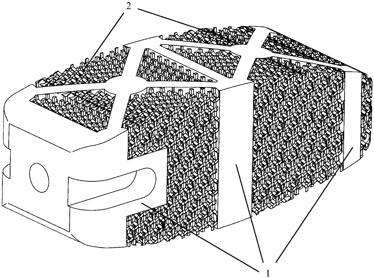
[0026] see Figure 5 with Image 6 The pore structure part of the porous titanium intervertebral fusion cage of this embodiment is a part of a fusion cage formed by integrally printing titanium alloy materials by a 3D printer, and the pore structure part 2 is composed of a combination of void units in a regular tetrahedral structure. ; Each void unit is composed of 4 rectangular parallelepiped cylindrical titanium pillars 21 with the same length connected together, that is, the respective ends of the 4 titanium pillars 21 are connected together, and the angle between each titanium pillar 21 is 109 The other end of each of the four titanium pillars 21 is connected to the other end of a titanium pillar corresponding to an adjacent void unit. The angle between the two connected titanium pillars is also 109 degrees and 28 minutes. That is, the connection mode between each titanium column 21 of the pore structure part and th...

Embodiment 2

[0028] (Example 2. Intervertebral fusion cage)

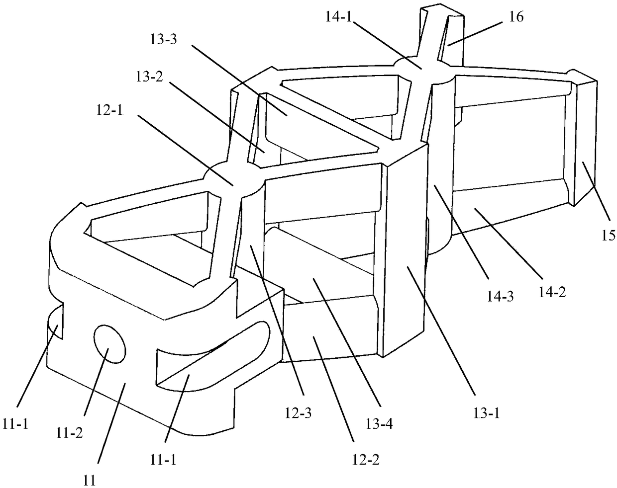
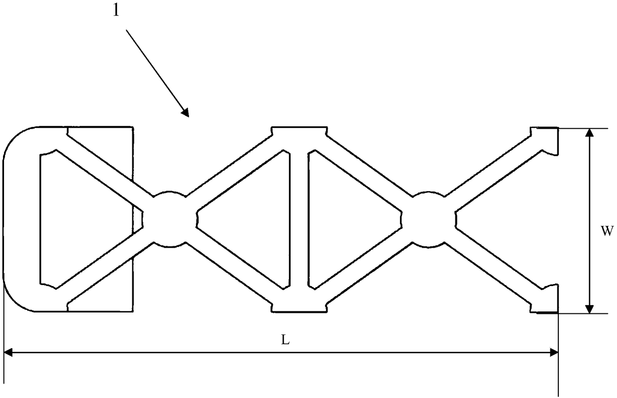
[0029] Such as figure 1 As shown, the intervertebral fusion cage of this application example is a structural part formed by integrally printing titanium alloy materials by a 3D printer. The pore structure device of the cage is divided into a supporting structure part 1 and a pore structure part 2 according to different functions. The supporting structure portion 1 and the pore structure portion 2 are integrally fixedly connected to each other. The supporting structure part 1 is used to bear the external load, and the pore structure part 2 is used to guide the growth of new bone; the volume of the supporting structure part 1 accounts for 10% of the total volume of the cage. The pore structure part 2 is exposed to the outside in an open manner on the upper, lower, front, back and right sides of the support structure part 1, and at corresponding locations on the front, back and right sides of the support structure part 1. It is loca...


PUM

PropertyMeasurementUnit
lengthaaaaaaaaaa
widthaaaaaaaaaa
thicknessaaaaaaaaaa

Abstract

The invention discloses a pore structure part of a porous titanium intervertebral fusion cage. The pore structure part is a part of a fusion cage printing forming titanium alloy material integrally through a 3D printer, and is used for leading new bone ingrowth. The pore structure part is composed of pore units of a regular tetrahedron structure; respective one ends of four titanium columns of each pore unit are connected together, the inclined angle between each titanium column and another is 109 degree 28 cent, meanwhile the other end of each titanium column is connected to the other end of one titanium column of a corresponding adjacent pore unit, and the inclined angle between the titanium columns is 109 degree 28 cent as well, that is the connection method of each titanium column of the pore structure part and the adjacent titanium column is arranged according to a method similar to the arrangement method of the chemical bond between each carbon atom and an adjacent carbon atom in diamond. The provided pore structure part of a porous titanium intervertebral fusion cage is good in intensity, and has certain elasticity and a certain intervertebral healing effect when in use.

Description

Technical field [0001] The invention relates to an implant for vertebrae, belonging to the field of intervertebral fusion and internal fixation, and in particular to a position of a porous titanium intervertebral fusion cage. Background technique [0002] Lumbar disc herniation and cervical spondylopathy and other symptoms of intervertebral disc degenerative disease are a common and frequently-occurring disease in modern society, which seriously affects the quality of life of patients. Spinal fusion is one of the most widely used techniques in spinal surgery. It mainly promotes spine osseous fusion by establishing immediate stability of the spine, bone formation, osteoinduction, and bone conduction of implants. At present, intervertebral fusion has become the main method for the treatment of lumbar instability, lumbar spinal stenosis, degenerative spondylolisthesis, degenerative scoliosis, false joints and degenerative disc disease. The fusion cages in the prior art are mainly d...

Claims


Application Information

Patent Timeline
Patent Type & Authority Patents(China)
IPC IPC(8): A61F2/44
CPCA61F2/30767A61F2/4455A61F2002/30199A61F2002/30593A61F2002/3093A61F2002/30985A61F2310/00023
Inventor 吴忆峰李翔陈文涛韦冬孙平阳
Owner CHANGZHOU WASTON MEDICAL APPLIANCE CO LTD
Why Eureka
Try Eureka