Wire spool for passing of wire through a rotational coupling

a technology of rotation coupling and wire spool, which is applied in the direction of surgical staples, surgical forceps, manufacturing tools, etc., can solve the problems of complicated application of clips or fasteners

Active Publication Date: 2013-10-29
COVIDIEN LP
View PDF15 Cites 871 Cited by
  • Summary
  • Abstract
  • Description
  • Claims
  • Application Information

AI Technical Summary

Benefits of technology

[0013]The surgical apparatus may include a limiting mechanism to restrict rotational movement of the elongate tubular member. The limiting mechanism includes an inner band and an outer collar and a ball bearing. The inner band defines a spiral cam slot and the outer collar defines a longitudinal cam slot. The ball bearing is located within both the spiral cam slot and the longitudinal cam slot. The spiral cam slot may traverse about the inner band about 700°. A neutral decent may be defined midway along the longitudinal cam slot to provide a tactile indication of a neutral position of the elongate tubular member. The elongate tubular member is prevented from further rotation by the ball bearing acting against either a proximal end or a distal end of the longitudinal cam slot.

Problems solved by technology

Consequently, application of clips or fasteners may be complicated by a reduced field of view or reduced tactile feedback for the user at the proximal end of the device.

Method used


Image

  • Wire spool for passing of wire through a rotational coupling
  • Wire spool for passing of wire through a rotational coupling
  • Wire spool for passing of wire through a rotational coupling

Examples


Embodiment Construction

[0036]Embodiments of surgical instruments in accordance with the present disclosure will now be described in detail with reference to the drawing figures wherein like reference numerals identify similar or identical structural elements. As shown in the drawings and described throughout the following description, as is traditional when referring to relative positioning on a surgical instrument, the term “proximal” refers to the end of the apparatus which is closer to the user and the term “distal” refers to the end of the apparatus which is further away from the user.

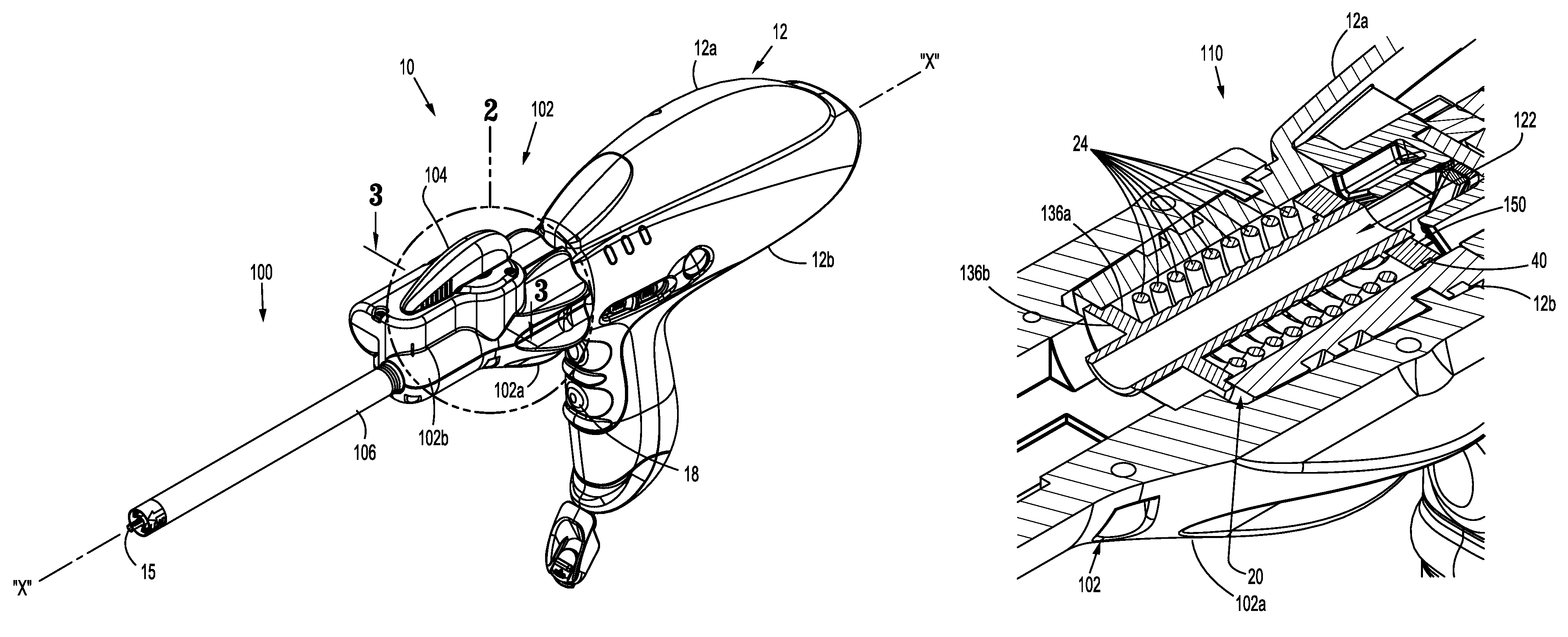
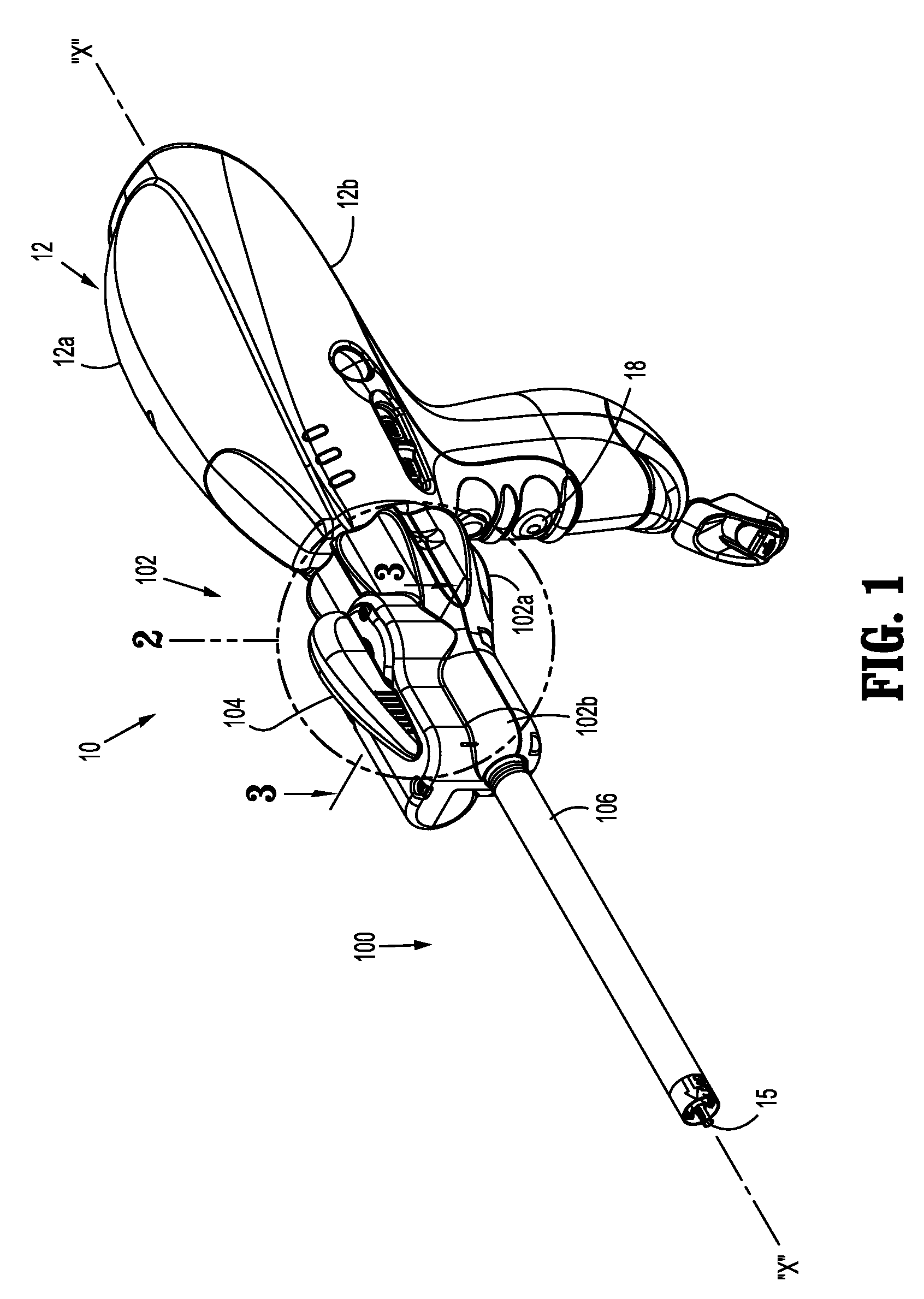
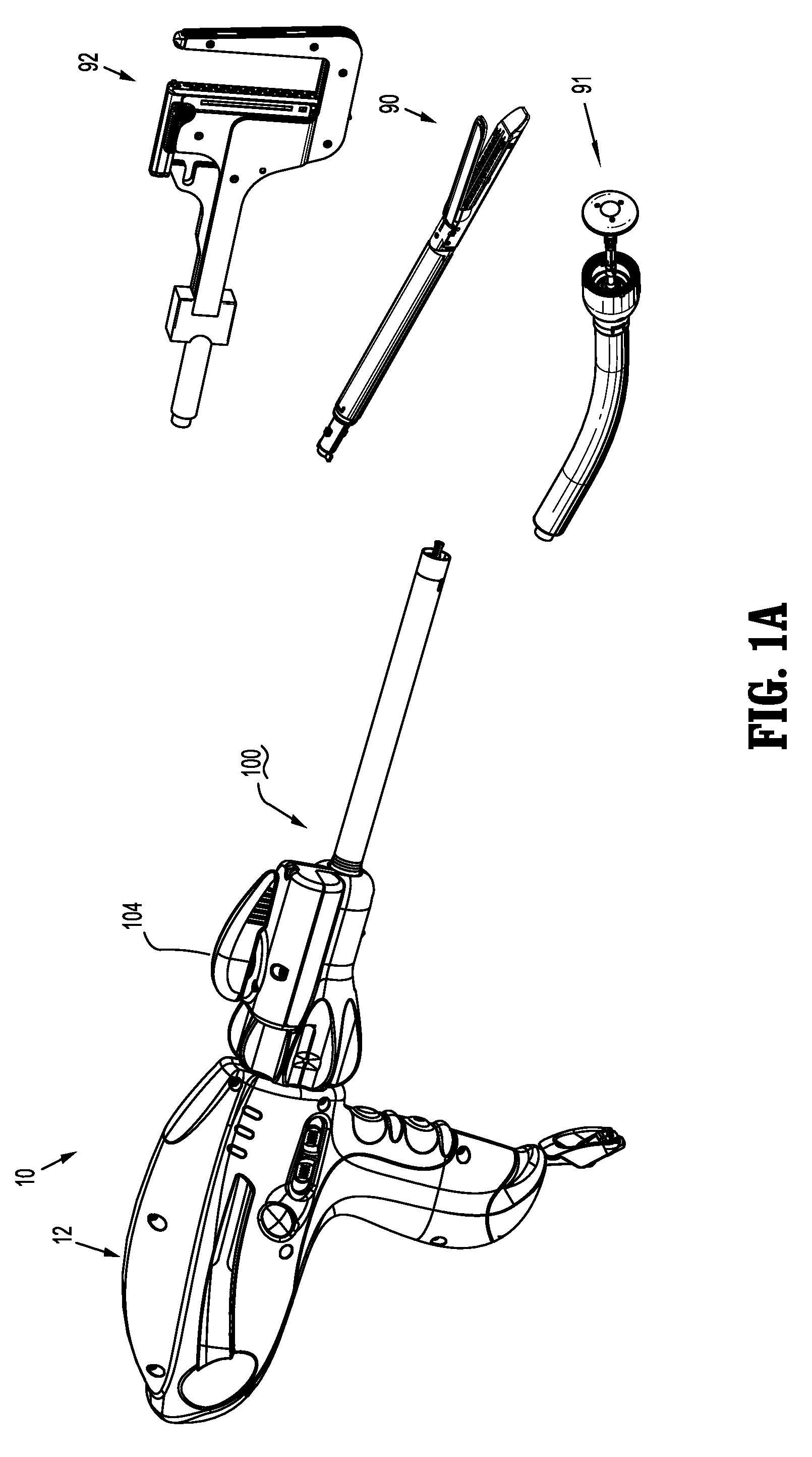
[0037]Referring now to the drawings, wherein like reference numerals identify identical or similar structural elements of the subject device through out the several views, there is illustrated in FIGS. 1-13, a surgical instrument, designated generally by reference numeral 10. U.S. patent application Ser. No. 11 / 786,933, filed on Apr. 13, 2007, the entire content of which is incorporated herein by reference, describes in ...


PUM

PropertyMeasurementUnit
rotationaaaaaaaaaa
electricalaaaaaaaaaa
movementaaaaaaaaaa

Abstract

A surgical apparatus for performance of a surgical procedure on body tissue is provided and includes a housing, an elongate tubular member, a drive assembly, an electrical coupling component, and an electrical wire. The elongate tubular member is at least partially supported by the housing and defines a center lumen and a longitudinal axis. The drive assembly extends from the housing into the center lumen of the elongate tubular member. The electrical coupling component is located about the drive assembly. The electrical wire extends from within the housing into the elongate tubular member. The electrical wire is wrapped about the electrical coupling component, which allows the elongate tubular member to rotate about the longitudinal axis while allowing the electrical wire to be fixed within the housing and the elongate tubular member.

Description

CROSS REFERENCE TO RELATED APPLICATION[0001]The present application claims the benefit of and priority to U.S. Provisional Application Ser. No. 61 / 408,800 filed on Nov. 1, 2010, the entire contents of which are incorporated herein by reference.BACKGROUND[0002]1. Technical Field[0003]The present disclosure relates to articulating and rotating surgical instruments. More specifically, the present disclosure relates to a coupling that allows articulation and rotation of an endoscopic portion of a surgical instrument, such as a clip applier, a surgical stapler and the like.[0004]2. Background of Related Art[0005]Endoscopic staplers and clip appliers are known in the art and are used for a number of distinct and useful surgical procedures. In the case of a laparoscopic surgical procedure, access to the interior of an abdomen is achieved through narrow tubes or cannulas inserted through a small entrance incision in the skin. Minimally invasive procedures performed elsewhere in the body are...

Claims


Application Information

Patent Timeline
Patent Type & Authority Patents(United States)
IPC IPC(8): A61B17/17
CPCA61B17/072A61B17/07207A61B17/1155A61B2017/00017A61B2017/00022A61B2017/00128A61B2017/00398A61B2017/00464A61B2017/00473A61B2017/2929
Inventor ROSS, ADAM J.ZEMLOK, MICHAEL A.
Owner COVIDIEN LP
Why Eureka
Try Eureka