

Electrical caulking gun
a caulking gun and electric technology, applied in the field of caulking guns, can solve the problems of affecting the operation efficiency of the caulking gun, the inability to pull the pushing rod backward manually, and the inability to operate the caulking gun. achieve the effect of high operation efficiency
- Summary
- Abstract
- Description
- Claims
- Application Information
AI Technical Summary
Benefits of technology
Problems solved by technology
Method used
Image

Examples
Embodiment Construction
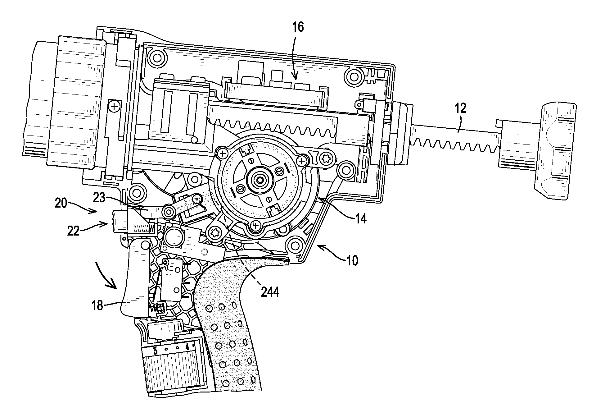
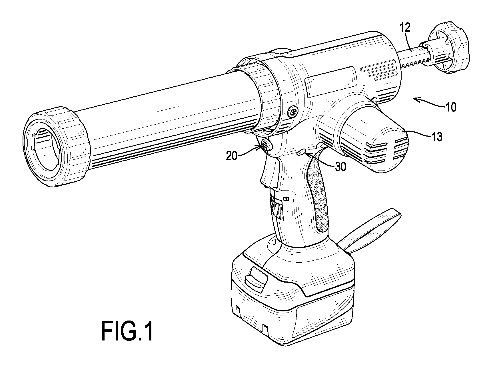
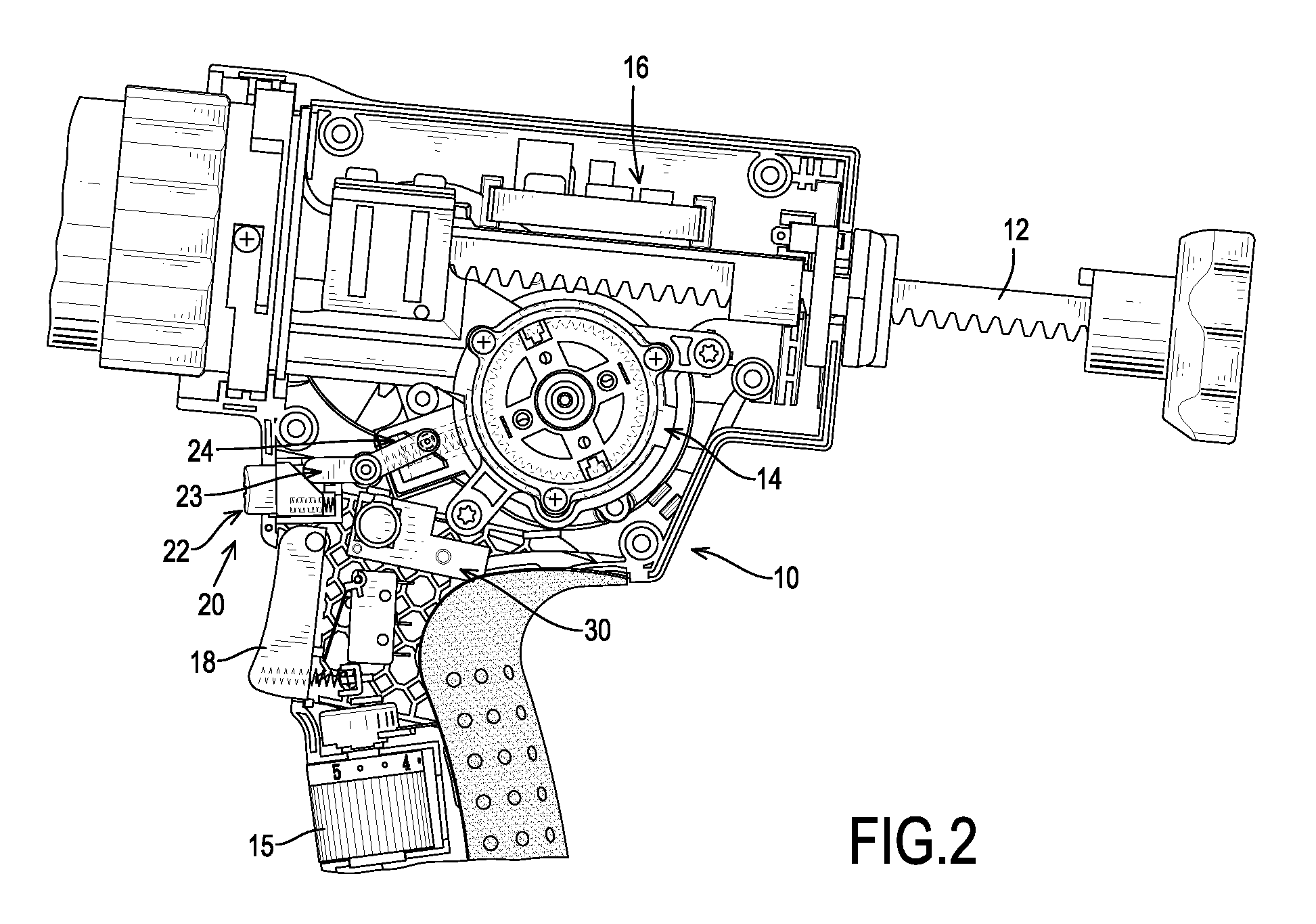
[0021]With reference to FIGS. 1 to 3 and 8, an electrical caulking gun in accordance with the present invention comprises a gun body 10, a pushing rod 12, a motor 13, a transmission device 14, a circuit board 16, a speed changing device 15, a trigger 18, a trigger switch 19, a clutching device 20 and a speed-changing switch 30. The pushing rod 12 is movably mounted on the gun body 10. The motor 13 is connected to and drives the pushing rod 12 to move relative to the gun body 10 with the transmission device 14. The transmission device 14 is mounted in the gun body 10 between the motor 13 and the pushing rod 12. The transmission device 14 may comprise sun gear set and a rack to transmit the power of the motor 13 to the pushing rod 12 so as to drive the pushing rod 12 to move relative to the gun body 10 and to release silicone from a tube. The circuit board 16 is mounted in the gun body 10 and is electrically connected to the motor 13. The speed changing device 15 is electrically conne...
PUM
 Abstract
Description
Claims
Application Information