Electro-optic displays, and color alters for use therein

a technology of optical displays and color filters, applied in optics, instruments, optical elements, etc., can solve the problems of inadequate service life of these displays, preventing their widespread use, and gas-based electrophoretic media being susceptible to the same types of problems

Active Publication Date: 2013-11-05
E INK CORPORATION
View PDF83 Cites 101 Cited by
  • Summary
  • Abstract
  • Description
  • Claims
  • Application Information

AI Technical Summary

Problems solved by technology

Nevertheless, problems with the long-term image quality of these displays have prevented their widespread usage.
For example, particles that make up electrophoretic displays tend to settle, resulting in inadequate service-life for these displays.
Such gas-based electrophoretic media appear to be susceptible to the same types of problems due to particle settling as liquid-based electrophoretic media, when the media are used in an orientation which permits such settling, for example in a sign where the medium is disposed in a vertical plane.
Indeed, particle settling appears to be a more serious problem in gas-based electrophoretic media than in liquid-based ones, since the lower viscosity of gaseous suspending fluids as compared with liquid ones allows more rapid settling of the electrophoretic particles.
However, the methods used for assembling LCD's cannot be used with solid electro-optic displays.
This LCD assembly process cannot readily be transferred to solid electro-optic displays.
However, attaching a color filter to an electro-optic display in the correction position is a difficult operation.
Many color filter arrays are formed on sheets of glass or similar rigid material in order that the color filter will maintain stable dimensions (even slight distortions of the dimensions of a color filter array can lead to at least part of the color filter array being misaligned with the pixels of the display, with consequent errors in the colors displayed to an observer).
However, the difficulties in alignment are exacerbated in flexible displays; when the display is not rigid, even if the alignment marks on one portion of the display are correctly aligned, this does not guarantee correct alignment over the whole backplane and color filter array, since the color filter array can flex and become deformed.
However, the resolution and alignment requirements imposed on such color filter formation processes are difficult to meet with most color filter formation technologies.
A color filter array have a resolution of 100 lines per inch will (if formed using parallel bands of three different colors) require the production of stripes only 1 / 300 inch (about 0.08 mm) wide, and producing such narrow stripes with no gaps between them and no overlap over the full width of a display several inches wide, and in accurate alignment with the pixels of a backplane present formidable challenges.
High resolution photolithography can achieve the necessary resolution and alignment, but three separate passes are required and the method is costly and time-consuming.
Attempts have been made to use ink jet printing or thermal transfer printing but no commercial products using these technologies have so far appeared.
Any color-forming technology, such as thermal transfer printing, which requires a separate pass for each color, will face difficulties in achieving the high degree of alignment needed between the multiple passes.
Furthermore, any technology which involves transfer of colored material to the front surface of an otherwise complete display may present problems with regard to the mechanical properties of the exposed viewing surface of the display.
Since the surface upon which the colored material is deposited may form (unless a separate cover layer is later attached) an external surface of the display, it is necessary that this material be both an appropriate material for reception of the colored material, and have the mechanical properties (for example, abrasion and scratch resistance) required in an external surface, and it may be difficult to find a material with the necessary combination of properties.

Method used


Image

  • Electro-optic displays, and color alters for use therein
  • Electro-optic displays, and color alters for use therein
  • Electro-optic displays, and color alters for use therein

Examples


Embodiment Construction

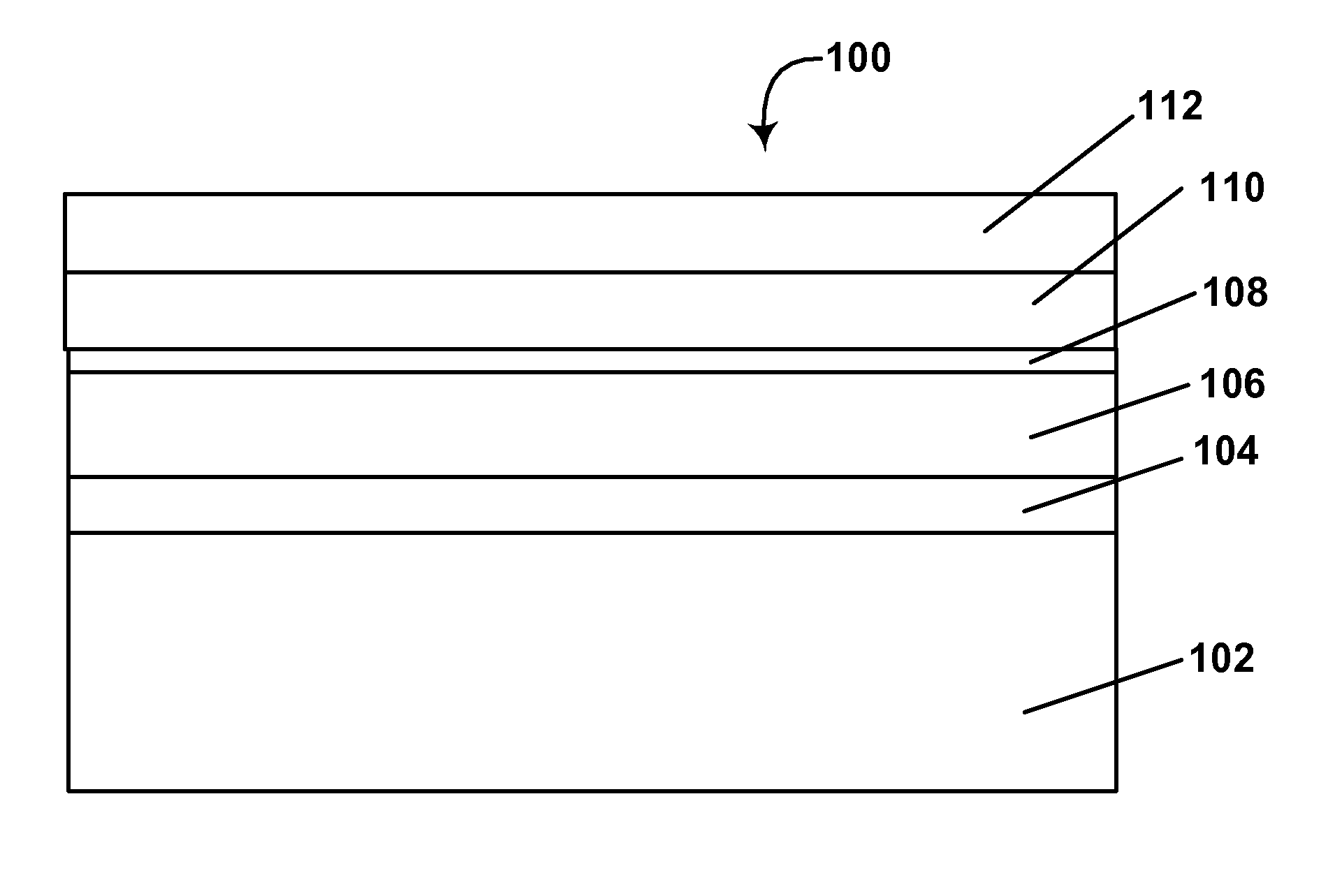
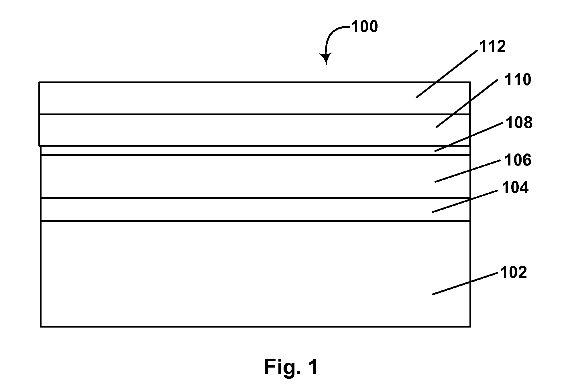
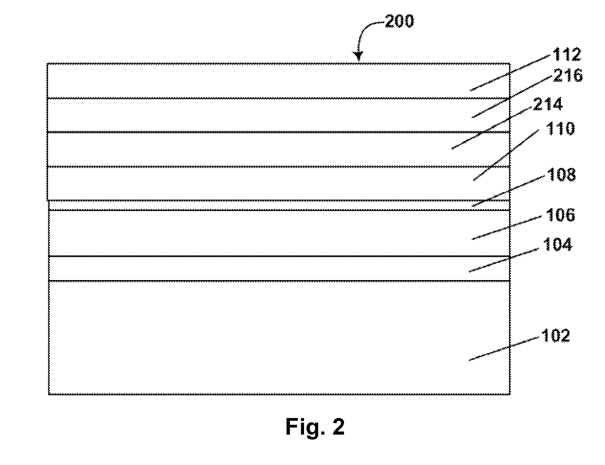
[0060]As already mentioned, the present invention provides a process for producing an electro-optic display having a color filter array. In this process, an electro-optic display is formed having a direct thermal imaging layer and a backplane having a two-dimensional array of pixel electrodes. The direct thermal imaging layer is then exposed to temperatures sufficient to form a plurality of differently colored areas in the direct thermal imaging layer, the plurality of differently colored areas being aligned with the two-dimensional array of pixel electrodes. The necessary alignment may be effected by detecting one or more features of the backplane, these features being either fiducial marks provided specifically for this purpose, or functional features, for example, row and column electrodes, already present in the backplane for other purposes. Thus, the present invention provides a simple, one step process for the creation of a color filter array on an otherwise completed display....


PUM

PropertyMeasurementUnit
diameteraaaaaaaaaa
thicknessaaaaaaaaaa
thicknessaaaaaaaaaa

Abstract

An electro-optic display having a color filter array is produced by attaching together a direct thermal imaging layer (112) and a backplane (102) having a two-dimensional array of pixel electrodes. The direct thermal imaging layer (112) is then exposed to temperatures sufficient to form a plurality of differently colored areas in the direct thermal imaging layer, the plurality of differently colored areas being aligned with the two-dimensional array of pixel electrodes.

Description

REFERENCE TO RELATED APPLICATIONS[0001]This application claims benefit of copending Provisional Application Ser. No. 61 / 350,637, filed Jun. 2, 2010.[0002]This application is also related to:[0003](a) U.S. Pat. No. 7,667,684;[0004](b) U.S. Pat. No. 6,864,875;[0005](c) U.S. Pat. No. 7,075,502; and[0006](d) U.S. Patent Application Publication No. 2010 / 0225995 (now U.S. Pat. No, 8,098,418).[0007]The entire contents of these copending application and these patents, and of all other U.S. patents and published and copending applications mentioned below, are herein incorporated by reference.BACKGROUND OF INVENTION[0008]This invention relates to electro-optic displays and color filters for use in such displays. More specifically, this invention relates to a method for producing such color filters which simplifies aligning the filter with the pixels of the electro-optic display.[0009]The term “electro-optic”, as applied to a material or a display, is used herein in its conventional meaning in...

Claims


Application Information

Patent Timeline
Patent Type & Authority Patents(United States)
IPC IPC(8): G02B26/00G02F1/29G02F1/167G02F1/1677
CPCG02F1/167G02F1/133516G02F1/1677
Inventor PAOLINI, JR., RICHARD J.ANSETH, JAY WILLIAM
Owner E INK CORPORATION
Why Eureka
Try Eureka