Space orientating mechanism with two tetrahedrons and eight arc-links

a space orientation and arc-linking technology, applied in the field of kinematic linkage systems, can solve the problems of high confinement of the moving range of the payload bay, three angles, namely the roll angle, the pitch angle and the yaw angle, and the less useful stewart platform for simulating high-maneuvering motion

Active Publication Date: 2013-11-12
TRUI WEN DER
View PDF8 Cites 31 Cited by
  • Summary
  • Abstract
  • Description
  • Claims
  • Application Information

AI Technical Summary

Benefits of technology

[0009]The primary objective of the present invention is to provide a space orientating mechanism, which significantly extends the range in three rotational DoF (Degree of Freedom), namely pitch, roll and yaw from the conventional 6-axis Stewart platform, and thus is able to simulate large-angle, high-maneuvering motion in the three-dimensional space as that performed by fighter planes or roller coasters.
[0010]Another objective of the present invention is to provide a space orientating mechanism, which increases two and three translational degrees of freedom for improving the shortage of the traditional gimbals type multi-ring mechanism, and providing passengers in the payload bay with virtual-but-real and shock-but-exciting feeling, wherein the mechanism may use motors as a torque source so as to be benefited by the controllability and maintainability of motors opposite to rotary hydraulic cylinders that limit the application of the mechanism to outdoor large amusement rides and military centrifuge training devices, thereby making the mechanism useful to indoor small playgrounds and aeronautical laboratories for physiology, among others.

Problems solved by technology

While a Stewart platform can be moved in six degrees of freedom, namely forward / backward, up / down, left / right, roll, pitch and yaw, the maximum extension of the linear actuator or the hydraulic cylinder driving it is substantially limited to the fixed length, causing the moving range of the payload bay highly confined.
Particularly, even with optimized design, the three angles, namely the roll angle, the pitch angle and the yaw angle, are still limited to ±45°.
Thus, although the 6-axis Stewart platform has been highly developed in these years, its innate insufficiency remains a problem and makes the Stewart platform less useful to simulate high-maneuvering motion in the three-dimensional space as that performed by high-speed vehicles, such as fighter planes and roller coasters, thereby limiting its application scope limited to airline flight training where only smooth take-off and landing are programmed accompanied with occasional interference caused by gusts.
However, since such a mechanism lacks for the translational degrees of freedom for up / down, left / right and forward / backward, it is incompetent when talking about stimulating passengers in the payload bay with sudden, scary vibration and shock.
In addition, with motors instead of rotary hydraulic cylinders used to output torque, the mechanism having less payload capacity and inefficient inertia would have its application scope significantly limited.
The defect of such a mechanism is out of the fact that its multiple rings are separately configured.
Therefore, the motor driving the middle ring has to bear the accumulated inertia of the motor-and-gear assemblies of both the payload bay and the inner ring, or it would fail to drive the middle ring to rotate against the pitch axis.
In this context, each of the rings must have significantly increased diameter to contain the corresponding motor and gearbox, resulting in the workspace of the overall mechanism too large and out of proportion to the payload capacity.
In addition, difficulty in electric communication can exist between the motors separately pivoted to the rings, and intertwisted wires may hinder the operation of the mechanism.
For these reasons, the gimbals type multi-ring mechanism is typically hydraulically driven, making it only suitable for the large multi-axis rolling amusement rides in theme parks, or for the anti-G centrifuge training devices specially designed for military use with less limitation to costs.

Method used


Image

  • Space orientating mechanism with two tetrahedrons and eight arc-links
  • Space orientating mechanism with two tetrahedrons and eight arc-links
  • Space orientating mechanism with two tetrahedrons and eight arc-links

Examples


Embodiment Construction

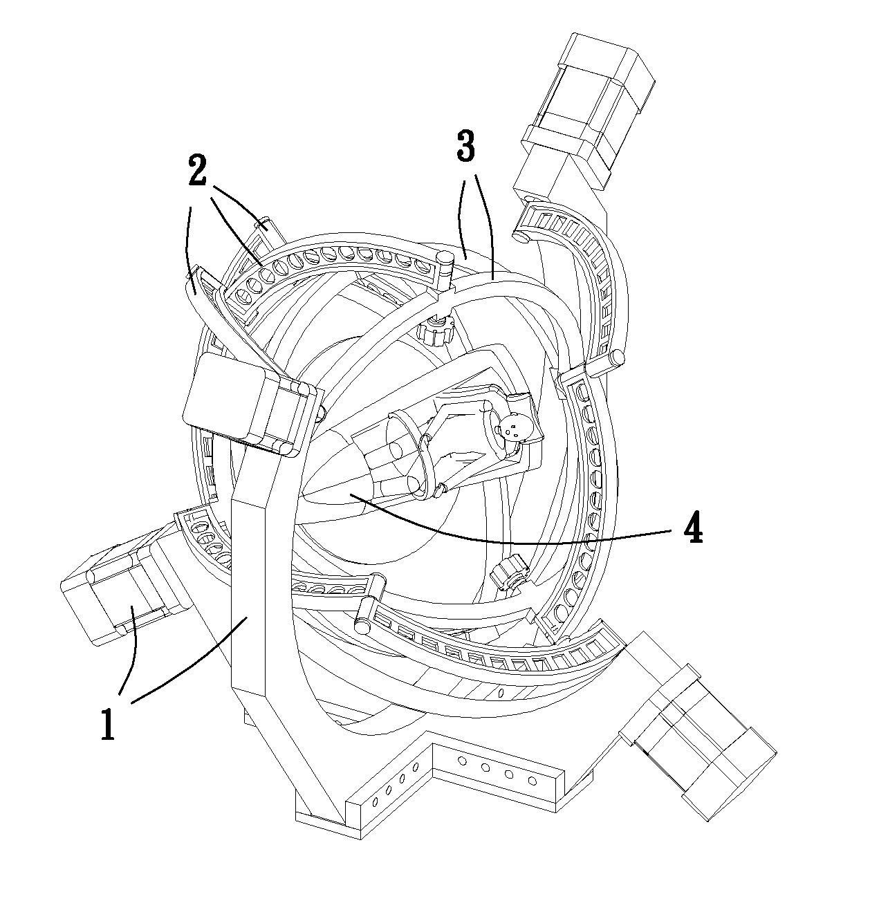
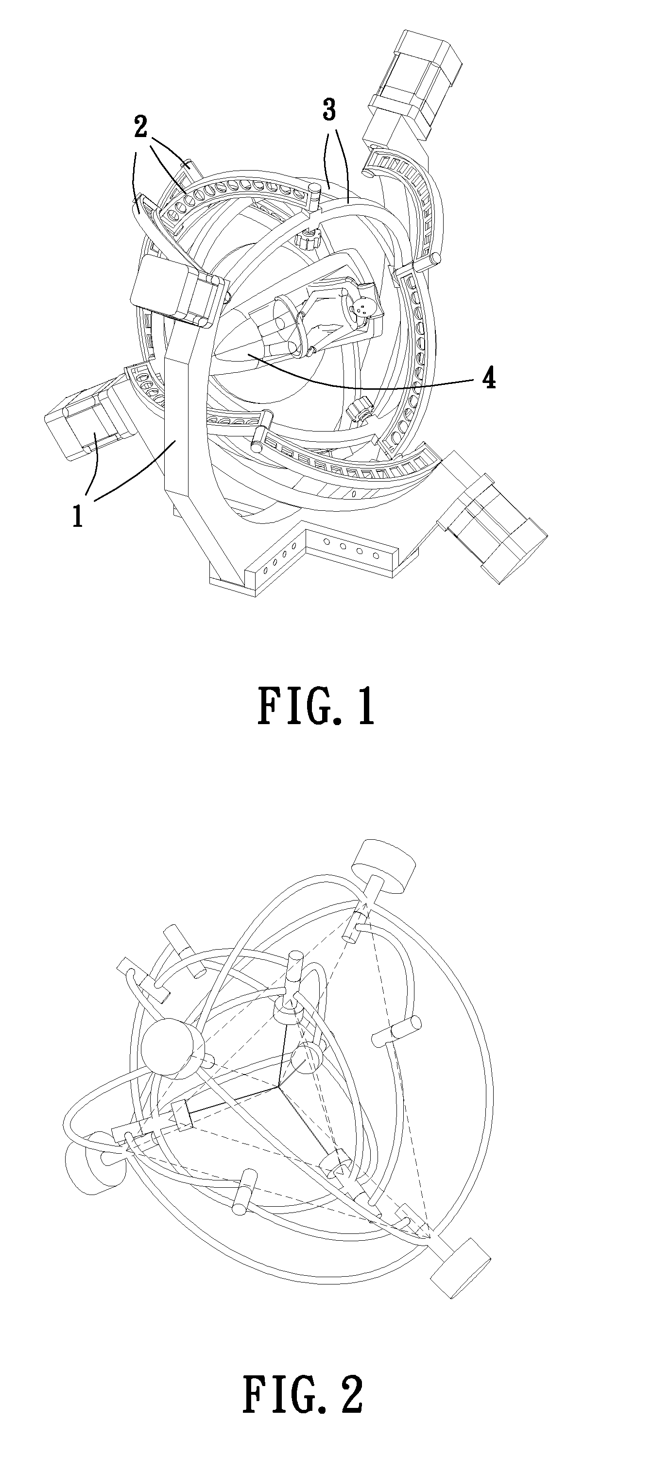
[0042]The mechanism of the present invention has the configuration as shown in FIG. 1, with the geometric definition as reflected in FIG. 2. For both of the structures, the features, geometric definitions and configurations of their components will be described separately for illustration.

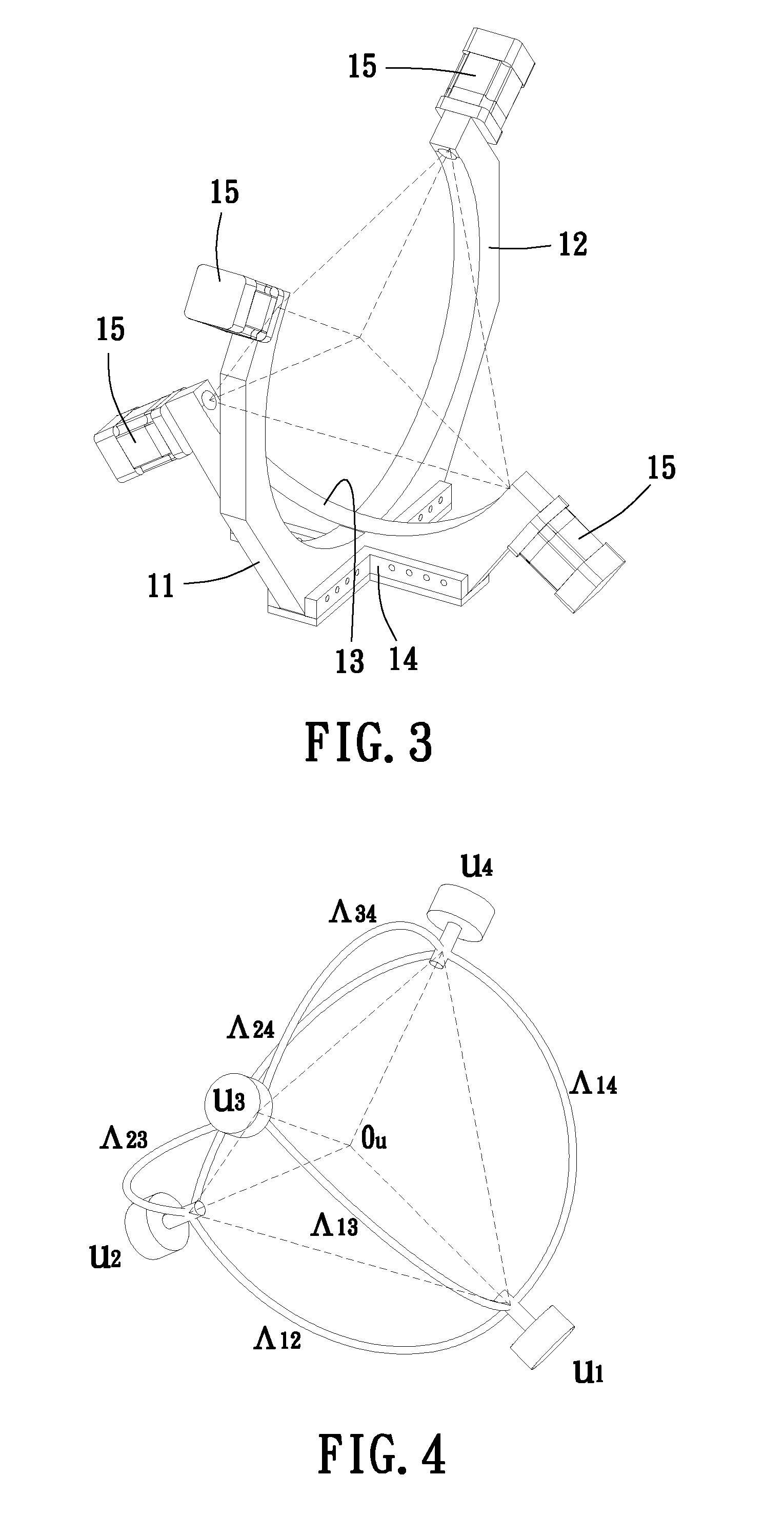
[0043]The disclosed mechanism has an outer tetrahedron frame (hereinafter also referred to as the outer frame), on which the four motors are fixedly mounted. The torque output devices shafted on the outer tetrahedron frame can be electric motors, hydraulic actuator or pneumatic actuator, but motors are advantageous for being easy to operate and maintain, hereinafter the torque output devices are collectively referred to as the motors. The outer frame may be composed of a left arc-bracket 11, a right arc-bracket 12, a lower arc-bracket 13, a cross bracket 14 and four motors 15, as shown in FIG. 3.

[0044]The outer tetrahedron frame has such a geometric definition that the four vertexes of the outer te...


PUM


Abstract

This new invented mechanism is geometrically defined by two concentric tetrahedrons. Four motors are mounted onto the four vertexes of an outer tetrahedron frame. Four outer arc-links which are driven by these motors are pivotally connected with another four inner arc-links which are pivoted by four vertexes of an inner tetrahedron frame. This mechanism not only extends the range in pitch, roll and yaw three rotational DoF for enlarging the limits of Stewart 6-axis motion platform but also increases two translational DoF for improving the shortage of gimbals type multi-ring mechanism. This mechanism can simulate high maneuvering motion (ex. Barrel roll or fast spin) as high-speed vehicles (ex. fighter or roller coaster) can to stimulate passengers with virtual-but-real and shocked-but-exciting sensation. This mechanism will be chosen as a motion platform or a space orientating mechanism for a theme park game machine or a military fighter trainer.

Description

BACKGROUND OF THE INVENTION[0001]1. Technical Field[0002]The present invention relates to kinematic linkage systems, and more particularly, to a space orientating mechanism that us configured to simulate high maneuvering motion as those performed by high-speed vehicles (ex. aerial vehicles or playground equipment) so as to stimulate its passengers with virtual-but-real and shock-but-exciting feeling, thus being a suitable motion platform or for military fighter trainers or game machines in theme parks.[0003]2. Description of Related Art[0004]Currently the motion platforms, or referred to as space orientating mechanisms, used in flight trainers or amusement rides are mainly 6-axis Stewart platforms and gimbals type multi-ring mechanisms.[0005]The 6-axis Stewart platform was introduced by Stewart and Gough in 1965, which employs six actuators that are fixed to the ground for positioning and posing a top plate. After years of efforts paid to mechanical and kinetic development thereof, ...

Claims


Application Information

Patent Timeline
Patent Type & Authority Patents(United States)
IPC IPC(8): A63G31/00
CPCF16M11/123A63G31/00F16M11/18
Inventor TRUI, WEN-DERLIN, SHU-CHING
Owner TRUI WEN DER
Why Eureka
Try Eureka