Vibrator element, vibrator, oscillator, and electronic apparatus
a vibrator and element technology, applied in the direction of oscillator, piezoelectric/electrostrictive/magnetostrictive device, piezoelectric/electrostriction/magnetostriction machine, etc., can solve the problem of large q-value deterioration degr
- Summary
- Abstract
- Description
- Claims
- Application Information
AI Technical Summary
Benefits of technology
Problems solved by technology
Method used
Image
Examples
first embodiment
[0038]Here, as an example of a vibrator element, a quartz crystal vibrator element using a quartz crystal as a substrate will be explained.
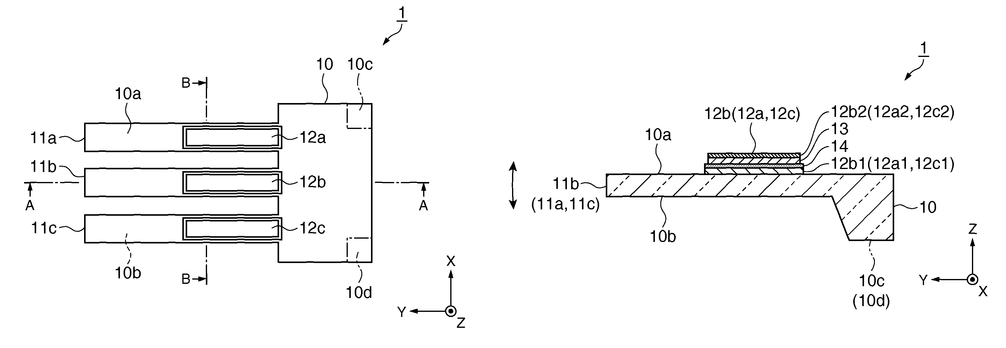
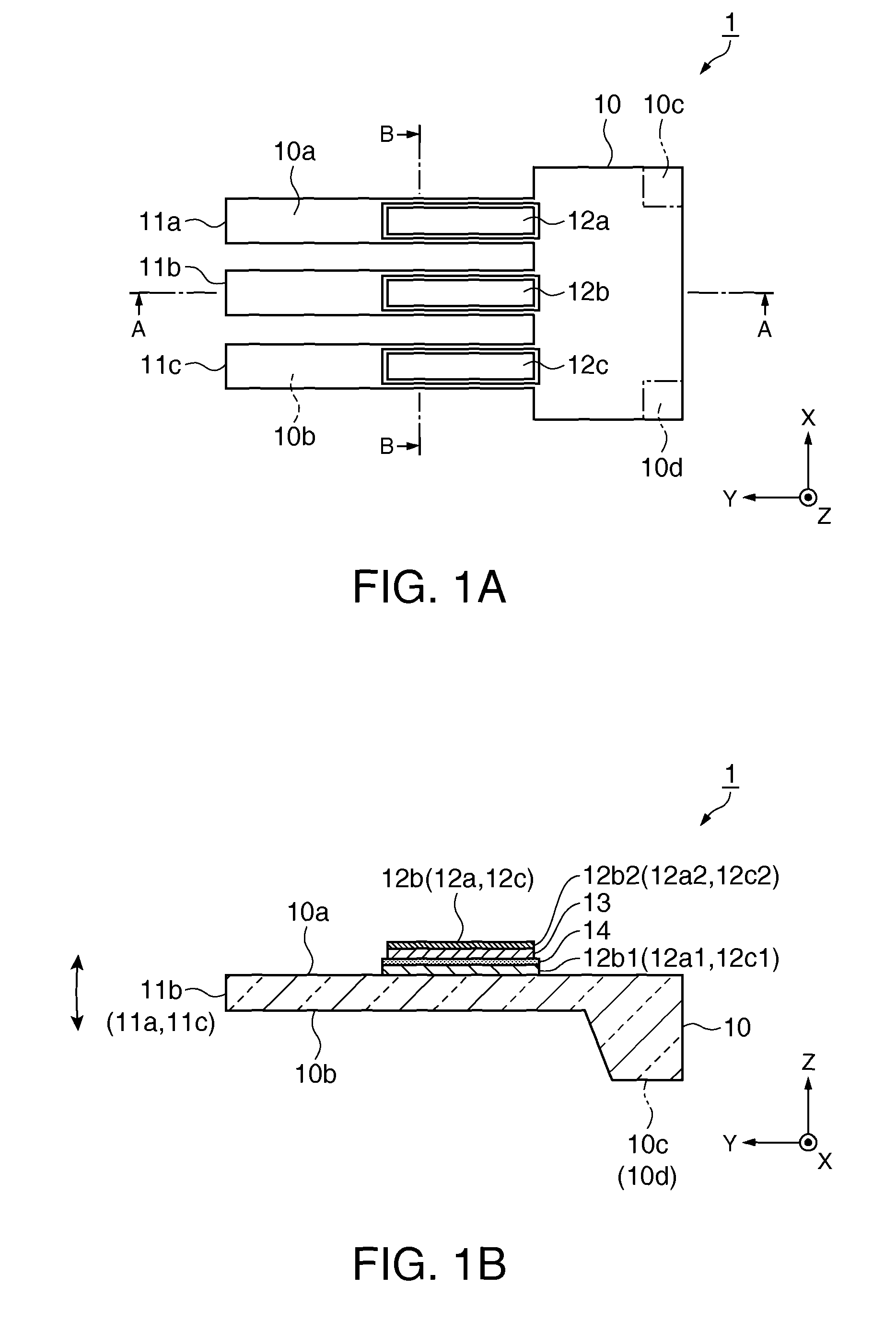
[0039]FIGS. 1A and 1B are schematic diagrams showing a general configuration of the quartz crystal vibrator element according to a first embodiment. FIG. 1A is a plan view, and FIG. 1B is a cross-sectional view of FIG. 1A along the line A-A. It should be noted that each wiring is omitted, and the dimensional ratios between the constituents are different from the real ones.
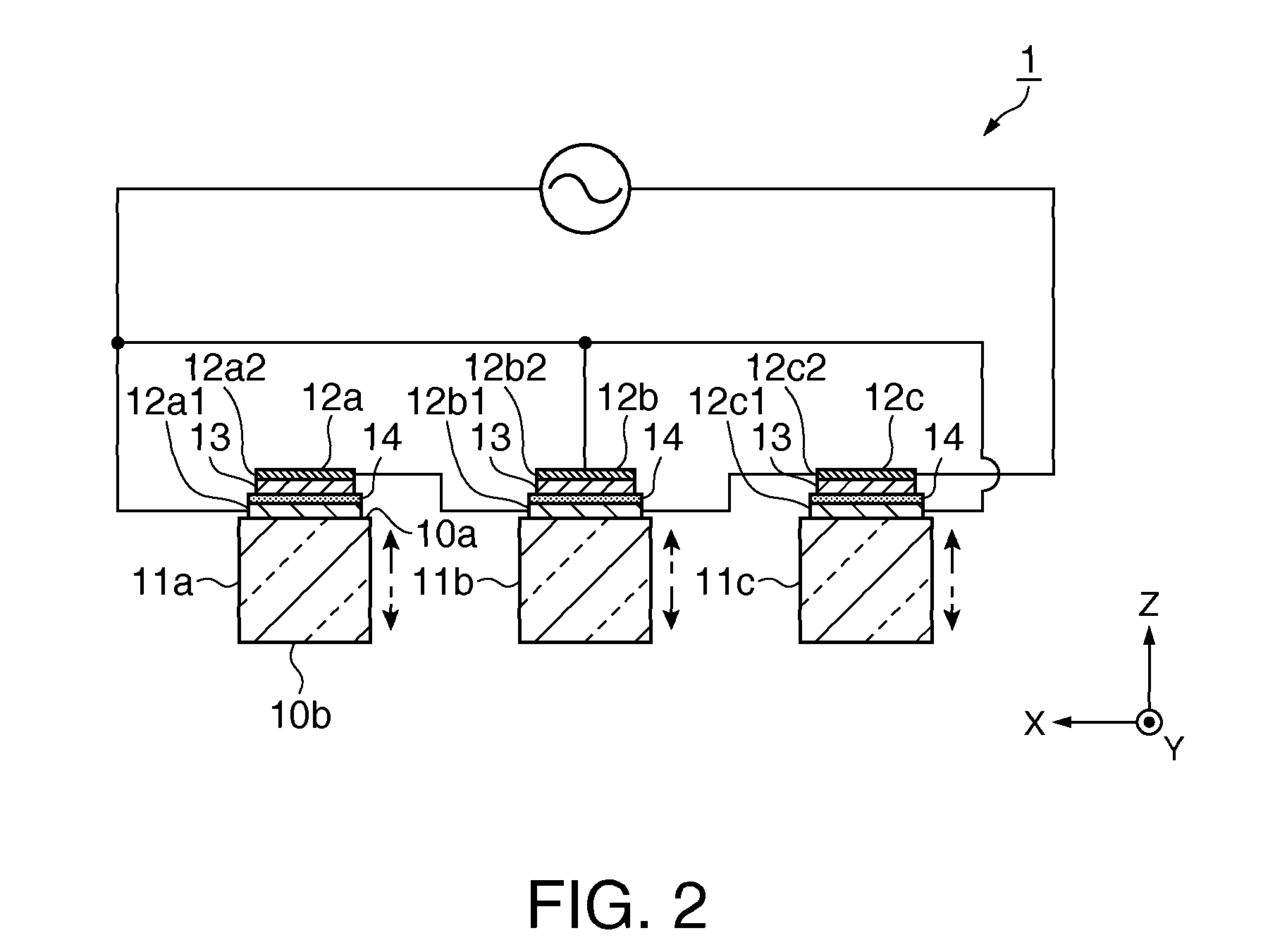
[0040]FIG. 2 is a cross-sectional view along the line B-B shown in FIG. 1A, and a wiring diagram of excitation electrodes.
[0041]As shown in FIGS. 1A and 1B, the quartz crystal vibrator element1 is provided with a base section 10 as a substrate, and three vibration arms 11a, 11b, and 11c each extending from the base section 10 in a Y-axis direction of the quartz crystal axis. In the present embodiment, a Z-cut quartz crystal substrate is used as the three vibration arms 11a, 11b,...
second embodiment
[0098]Then, a quartz crystal vibrator as a vibrator equipped with the quartz crystal vibrator element described above in the first embodiment will be explained.
[0099]FIGS. 4A and 4B are schematic diagrams showing a general configuration of the quartz crystal vibrator according to the second embodiment. FIG. 4A is a plan view looked down from a lid (lid body) side, and FIG. 4B is a cross-sectional view along the line C-C shown in FIG. 4A. It should be noted that the lid is omitted in the plan view. Further, the wires are also omitted.
[0100]It should be noted that the sections common to the first and second embodiments are denoted with the same reference numerals, and the detailed explanation therefor will be omitted, while the sections different from those of the first embodiment described above will mainly be explained.
[0101]As shown in FIGS. 4A and 4B, the quartz crystal vibrator 5 is provided with either one (here, the quartz crystal vibrator element 1) of the quartz crystal vibra...
third embodiment
[0122]Then, a quartz crystal oscillator as an oscillator equipped with the quartz crystal vibrator element described above in the first embodiment will be explained.
[0123]FIGS. 5A and 5B are schematic diagrams showing a general configuration of the quartz crystal oscillator according to a third embodiment. FIG. 5A is a plan view looked down from the lid side, and FIG. 5B is a cross-sectional view along the line C-C shown in FIG. 5A. It should be noted that the lid and some of the constituents are omitted in the plan view. Further, the wires are also omitted.
[0124]It should be noted that the sections common to the first through third embodiments are denoted with the same reference numerals, and the explanation therefor will be omitted, while the sections different from those of the first and second embodiments described above will mainly be explained.
[0125]As shown in FIGS. 5A and 5B, the quartz crystal oscillator 6 is provided with either one (here, the quartz crystal vibrator eleme...
PUM
 Abstract
Description
Claims
Application Information
 - R&D
- Intellectual Property
- Life Sciences
- Materials
- Tech Scout
- Unparalleled Data Quality
- Higher Quality Content
- 60% Fewer Hallucinations
Browse by: Latest US Patents, China's latest patents, Technical Efficacy Thesaurus, Application Domain, Technology Topic, Popular Technical Reports.
© 2025 PatSnap. All rights reserved.Legal|Privacy policy|Modern Slavery Act Transparency Statement|Sitemap|About US| Contact US: help@patsnap.com


