Medical X-ray apparatus

a technology of x-ray apparatus and x-ray beam, which is applied in the field of medical x-ray apparatus, can solve the problems of not disclosing or suggesting restriction of x-ray beam in the direction of intersecting scanning directions, and achieve the effect of reducing the exposure amoun

Active Publication Date: 2013-11-19
MORITA MFG CO LTD
View PDF18 Cites 17 Cited by
  • Summary
  • Abstract
  • Description
  • Claims
  • Application Information

AI Technical Summary

Benefits of technology

[0034]According to the present invention, the direction intersecting with scan direction is defined as a height direction, at least one of both ends of width of the X-ray beam in the height direction is set at an optional position in accordance with the position of an interested area of the object, and the X-ray restricted in the height direction is irradiated only on the interested area of the object, thereby reducing X-ray exposure amount on the object.
[0035]According to the structure in which the width of the X-ray beam in scan direction intersecting with the height direction of the X-ray radiation area is restricted, the X-ray amount exposed on the object can be further reduced.
[0036]According to the structure in which a position of at least one of both ends of the width of the X-ray beam in the height direction of the X-ray radiation area is changed in the height direction, the width of the X-ray in the height direction can be dynamically changed depending on the shape of the interested area, thereby reducing the X-ray exposure amount on the area around the interested area.
[0037]According to the structure wherein the medical X-ray apparatus comprises a moving mechanism for moving the supporting part at least in the height direction with respect to the object to change the radiating position of the X-ray beam in the height direction, the scan driving part displaces the X-ray radiation area of the X-ray beam in the height direction, so that the structure of the radiation area restricting part in the X-ray generating part can be simplified and can be downsized.
[0038]According to the structure in which the medical X-ray apparatus further comprises a driving mechanism for driving the radiation area restricting part, the radiation area restricting part comprises an open part having an opening for passing through the X-ray beam, and the driving mechanism changes the position of at least one of both ends of the width of the opening in the height direction corresponding to the interested area of the object, the supporting part is not required to be moved in the height direction, so that the driving mechanism of the supporting par can be simplified.
[0039]According to the structure in which the open part comprises a slit member having a slit restricting the X-ray beam in slit-like form and a shielding member for restricting at least one end and the other end in the height direction of the slit so as to have variable shielding amount, the X-ray radiation area of the X-ray beam can be displaced in the height direction only by controlling the shielding member, so that a large scale driving mechanism is not necessary, thereby reducing the cost.

Problems solved by technology

In addition, the panoramic radiography apparatus in the patent citation 2 discloses restriction of X-ray beam in a scanning direction, however, it does not disclose or suggest restriction of X-ray beam in a direction intersecting a scanning direction.

Method used


Image

  • Medical X-ray apparatus
  • Medical X-ray apparatus
  • Medical X-ray apparatus

Examples


second embodiment

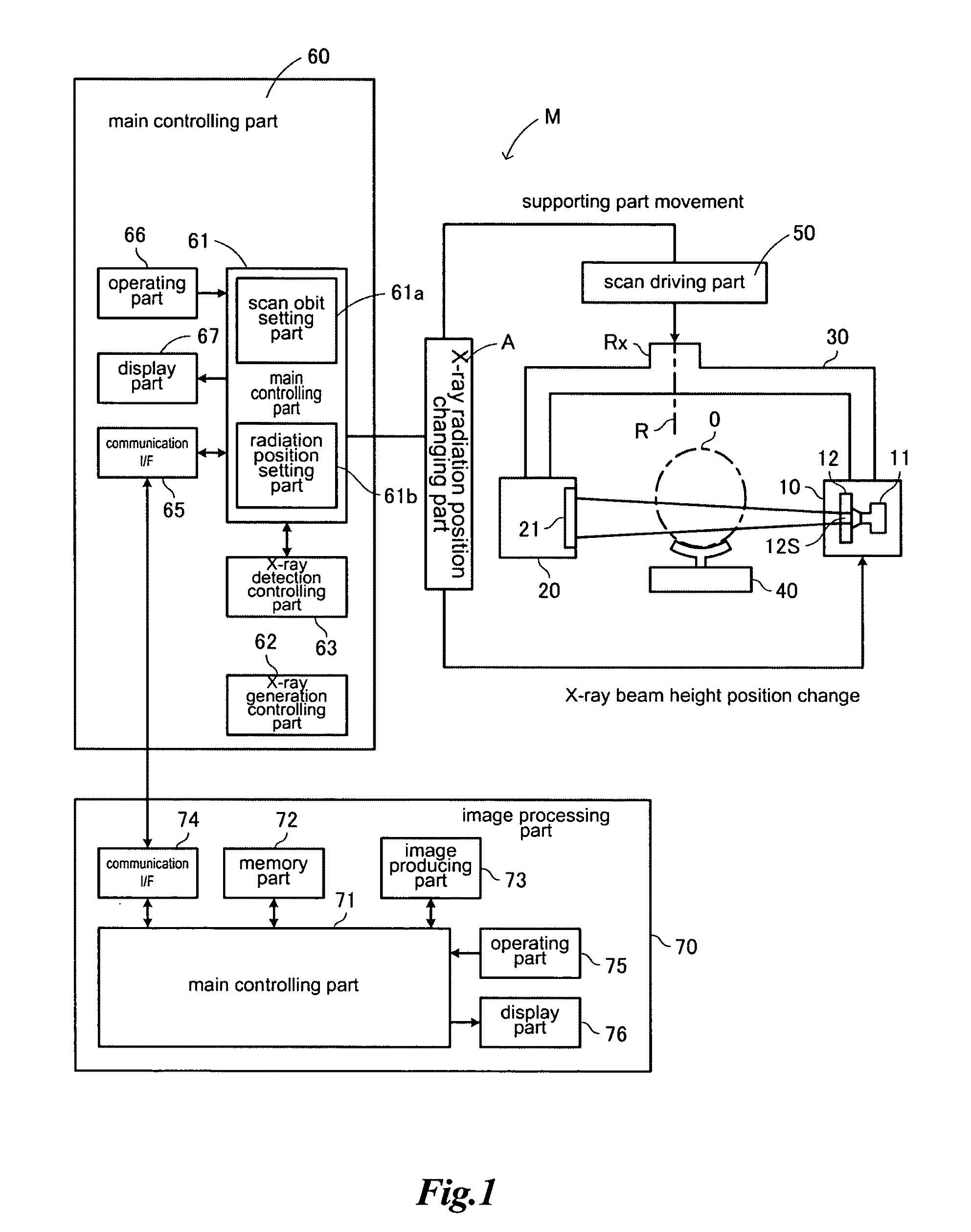
[0103]The scan driving part 50 is in particular constituted with an X-Y table as mentioned in the second embodiment later.

[0104]The supporting part 30 is provided with a rotary shaft (shaft portion) Rx. The supporting part 30 is designed to be rotatable around a rotary shaft R at the shaft portion Rx, to be strict, around the rotary shaft R at the shaft center Rxc of the shaft portion Rx.

[0105]When the supporting part 30 rotates around the shaft center Rxc, the X-ray generator 11 and the X-ray detector 21 rotate around the shaft center Rxc as shown in the figure. The rotary shaft R of the supporting part 30 and the rotary shaft R of the X-ray generator 11 and the X-ray detector 21 may not conform to the mechanical shaft center Rxc of the rotary shaft Rx.

[0106]For example, in the structure in Japanese patent publication JP-2007-29168-A which is an application of the present applicant, the composite motion by the simultaneous interaction of rotation of the rotary means and movement of...

third embodiment

[0194]The basic idea of the present invention is also utilized in a third embodiment mentioned later.

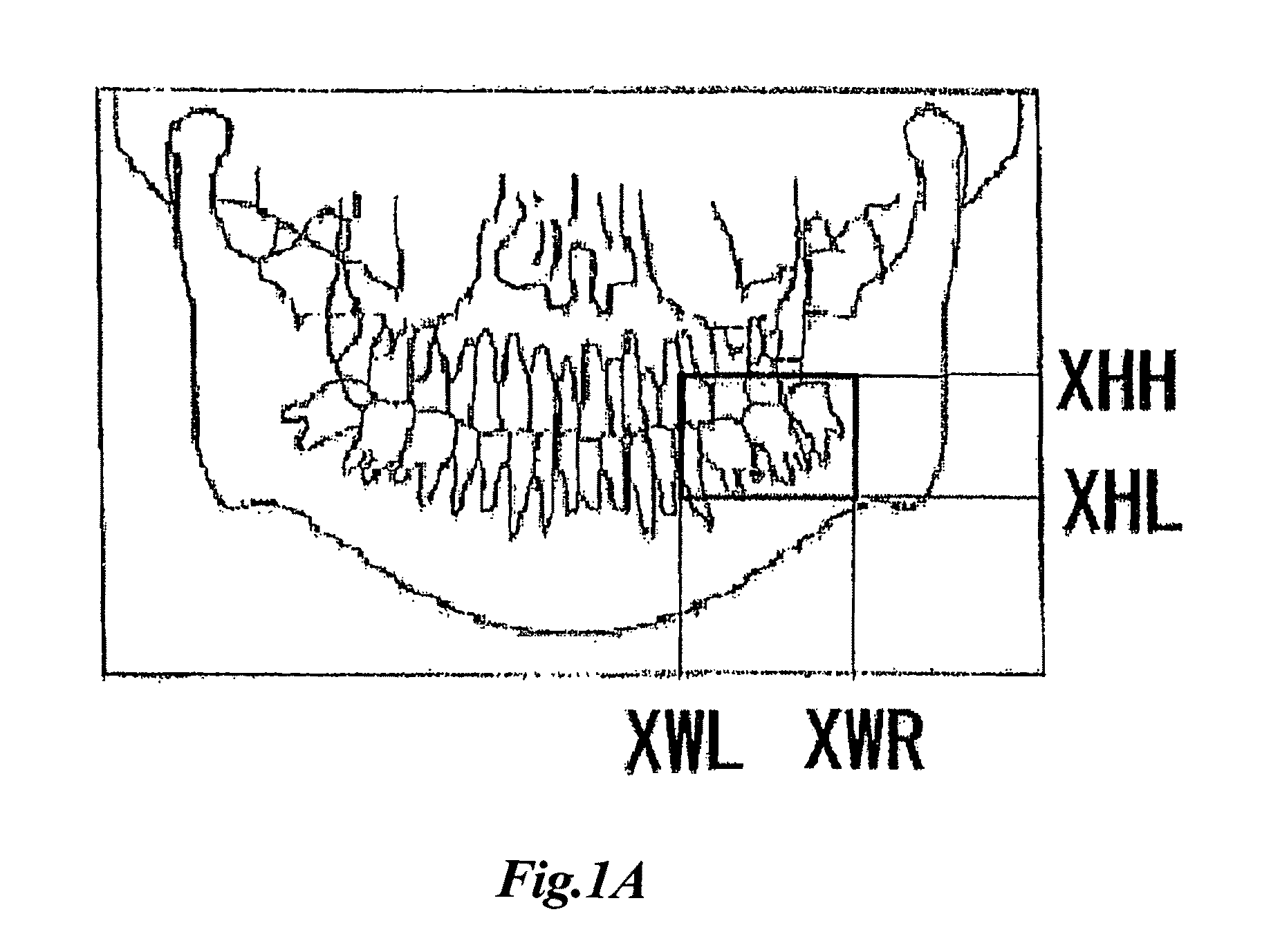
[0195]In a scan control example of the X-ray beam XB shown in FIGS. 13a and 13b mentioned later, while the X-ray beam XB is moved in the scanning direction HD, X-ray is irradiated by changing the diaphragm of the X-ray beam XB or the distance VW thereof in the height direction to be wider or narrower in accordance with a radiography region of the object “O”, and at least one of the both ends of the width of the X-ray beam in the height direction is restricted in the height direction depending on the radiography area position and its shape.

[0196]Accordingly, as a result of such scanning with the X-ray beam XB, it is made possible in the present invention to obtain a panoramic X-ray image as shown in FIG. 11a and FIG. 14 mentioned later without exposure to X-ray in areas other than the interested area “r” of the object “O”.

[0197]Like an example of FIG. 13c mentioned later, while settin...

fourth embodiment

[0330]the medical X-ray apparatus according to the present invention is explained hereinafter with reference to drawings.

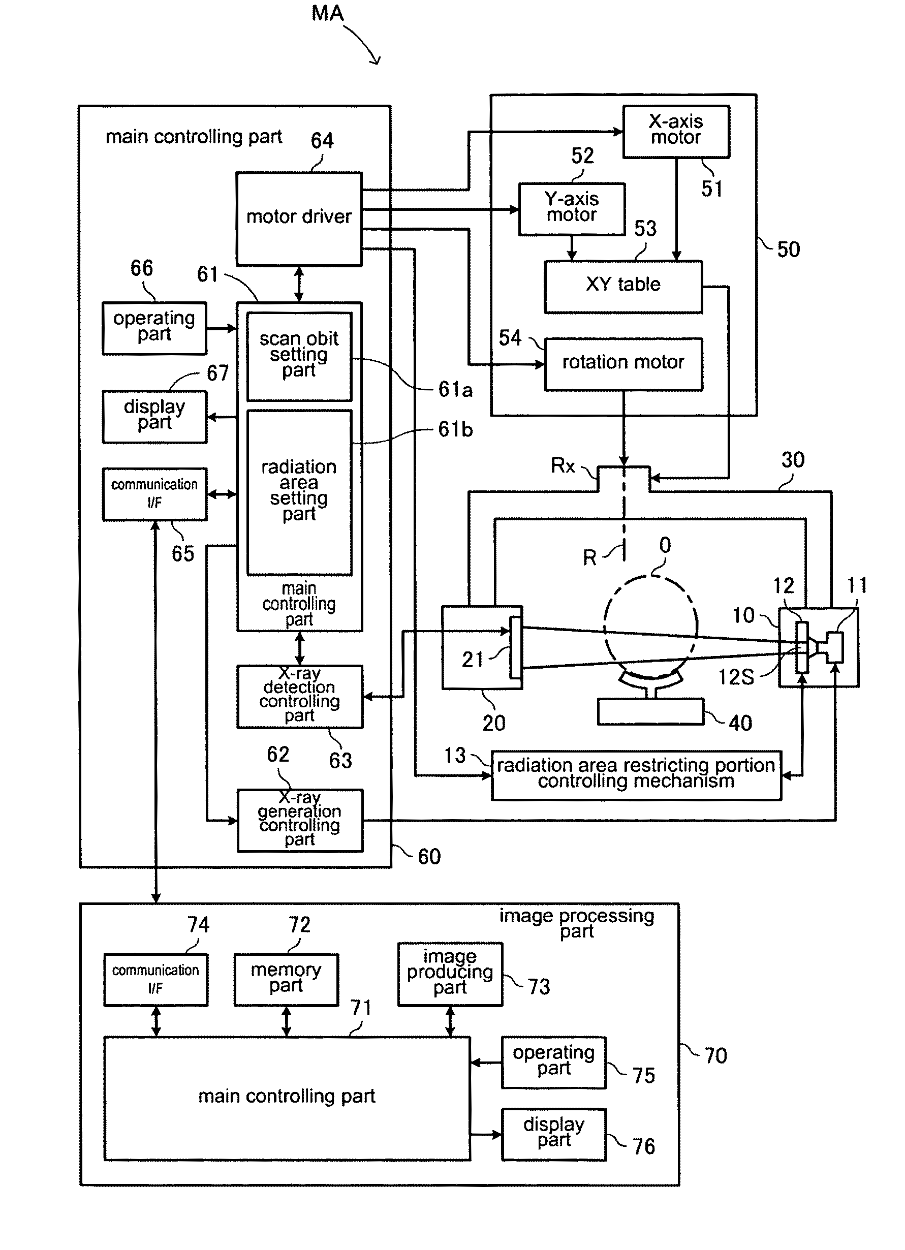
[0331]FIG. 22 is a block diagram showing a basic structure of a medical X-ray apparatus MB.

[0332]This embodiment is characterized by controlling an X-ray radiation area by a supporting part moving mechanism. In the example of FIG. 22, a supporting part moving mechanism 13A is structured to further include the scan driving part 50, wherein the same reference numbers refer to parts used for the same purpose as the medical X-ray apparatus M shown in FIG. 1 and detailed explanation thereof is omitted.

[0333]The medical X-ray apparatus MB according to the present embodiment has the supporting part moving mechanism 13A, and the support moving mechanism 13A includes the rotary motor 54 for rotating the supporting part 30, a Z-axis motor 55 for displacing the supporting part 30 in the height direction (or Z-axis direction), and a Z-axis table 56 driven by the Z-axis motor ...


PUM


Abstract

A medical X-ray apparatus comprising a supporting part for supporting an X-ray generator and a two-dimensional X-ray detector while interposing an object to be examined therebetween, a radiation area restricting part for restricting a radiation area of X-ray generated from the X-ray generator, and a scan driving part for scanning the object with the X-ray restricted by the radiation area restricting part as X-ray beam and for executing radiography. A direction intersecting with X-ray scan direction is defined as a height direction, the apparatus further comprises a radiation area setting part for setting at least one of both ends of width of the X-ray beam in the height direction at a desired position in accordance with the position of an interested area of the object; and the X-ray beam is irradiated only to the radiation area as set by the radiation area setting part with its beam width in height direction restricted by the radiation area restricting part.

Description

TECHNICAL FIELD[0001]The present invention relates to a medical X-ray apparatus for obtaining the information on a curved sectional plane by X-ray projection and obtaining a two-dimensional panoramic X-ray image.BACKGROUND ART[0002]A medical X-ray apparatus has an X-ray generator for projecting X-ray and an X-ray detector for receiving the X-ray from the X-ray generator, receives the X-ray generated at the X-ray generator and transmitted through an object to be examined, thereby obtaining an X-ray transmitted image based on the transmitted X-ray amount. In case of panoramic radiography, X-ray is projected while the X-ray generator and the X-ray detector are moved around the object along a predetermined orbit and a two-dimensional panoramic X-ray image of a curved sectional plane is obtained.[0003]The applicant of this invention has proposed a digital panoramic radiography apparatus in which the X-ray detector is a two-dimensional X-ray detector and a panoramic X-ray image on an opti...

Claims


Application Information

Patent Timeline
Patent Type & Authority Patents(United States)
IPC IPC(8): A61B6/14
CPCA61B6/14A61B6/4233A61B6/469
Inventor SUZUKIYOSHIKAWA, HIDEKIYOSHIMURA, TAKAHIROHONJO, MAKOTO
Owner MORITA MFG CO LTD
Why Eureka
Try Eureka