Signal generation circuit, frequency measurement device including the signal generation circuit, and signal generation method

a signal generation circuit and frequency measurement technology, applied in the field of frequency measurement, can solve problems such as inability to adapt to sensor arrays, and achieve the effects of improving frequency measurement resolving power, simple circuit, and suppressing pattern noise generation

Active Publication Date: 2013-11-26
SEIKO EPSON CORP
View PDF307 Cites 0 Cited by
  • Summary
  • Abstract
  • Description
  • Claims
  • Application Information

AI Technical Summary

Benefits of technology

[0008]In accordance with an advantage of some aspects of the invention, it is possible to provide a frequency change measuring device with an improved frequency measurement resolving power using a relatively simple circuit. In particular, it is possible to provide a signal generation circuit that may be used to suppress generation of pattern noise that could be generated in a frequency measurement device and the like.
[0010]By the structure described above, it is possible to generate a variable rate frequency-divided signal that includes frequency components of the first frequency-divided signal and frequency components of the second frequency-divided signal at a predetermined mixing ratio. It is noted here that the first frequency-divided signal and the second frequency-divided signal can be readily generated by a digital circuit based on the first signal. In other words, the variable rate frequency-divided signal described above can be generated without using an analog circuit that would likely become large in circuit scale. Also, the signal generation circuit having the structure described above is suitable to be used in a frequency measurement device, and can suppress generation of pattern noise that can occur in the frequency measurement device.
[0015]By the frequency measurement device having the structure described above, by composing at least the signal generation circuit by a digital circuit, the ratio of analog circuits to be used in the device can be reduced, such that the device can be made smaller in size and achieve power saving.
[0018]According to the frequency measurement device having the structure described above, the noise level in the frequency measurement can be suppressed by using the first frequency-divided signal and the second frequency-divided signal.
[0021]According to the frequency measurement device having the structure described above, the noise level in the frequency measurement using the device can be effectively suppressed.
[0029]The method described above makes it possible to generate a variable rate frequency-divided signal in which frequency components of the first frequency-divided signal and frequency components of the second frequency-divided signal are mixed in a specified mixing ratio in a dispersed manner.

Problems solved by technology

As errors that could occur at the time of measurement, plus / minus 1 count errors and errors caused by jitter at trigger level could occur, and in addition, errors that originate from the oscillation stability of the quartz oscillators would be superposed on the foregoing errors.
The use of reciprocal system counters may supplement for the deficiencies described above, but would not be suitable for a sensor array that is equipped with many sensors, because the circuit scale of each of the counters becomes large.

Method used


Image

  • Signal generation circuit, frequency measurement device including the signal generation circuit, and signal generation method
  • Signal generation circuit, frequency measurement device including the signal generation circuit, and signal generation method
  • Signal generation circuit, frequency measurement device including the signal generation circuit, and signal generation method

Examples


embodiment example 1

[0135]4. Embodiment Example 1

[0136]Hereinbelow, referring to FIGS. 19 through 26, Embodiment 1 in accordance with an embodiment of the invention will be described.

[0137](1) Exemplary Structure of Frequency Measurement Device

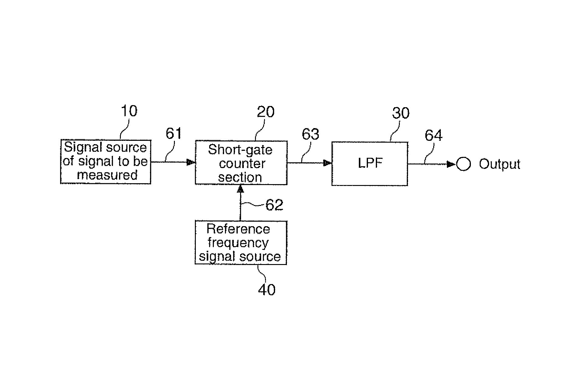
[0138]FIG. 19 is a diagram of a first exemplary structure of a frequency measurement device equipped with a variable rate frequency divider section 50. As shown in FIG. 19, the frequency measurement device is structured with a signal source of signal to be measured 10, a reference frequency signal source 40, a variable rate frequency divider section 50, a short gate counter section 20, and a low-pass filter 30. It is noted here that the signal source of signal to be measured 10, the short gate counter section 20 and the low-pass filter 30 have basically the same structure and function as those of the frequency measurement device described above with reference to FIG. 1, and therefore their description is omitted.

[0139]Reference Frequency Signal Source 40

[0140]The...

embodiment 2

[0174]5. Embodiment 2

[0175]Embodiment 2 in accordance with an embodiment of the invention will be described below with reference to FIGS. 27-31.

[0176](1) Exemplary Structure of Frequency Measurement Device

[0177]FIG. 27 is a diagram showing a second exemplary structure of the frequency measurement device equipped with the variable rate frequency divider section 50. As shown in FIG. 27, the frequency measurement device is structured with a signal source of signal to be measured 10, a reference frequency signal source 40, a variable rate frequency divider section 50, a short gate counter section 20, and a low-pass filter 30. Compared to the first exemplary structure of the frequency measurement device shown in FIG. 19, the second exemplary structure is different in that the variable rate frequency divider section 50 is not disposed between the reference frequency signal source 40 and the short gate counter section 20, but is disposed between the signal source of signal to be measured 1...


PUM


Abstract

A signal generation circuit includes: a first signal source that generates a first signal; and a variable rate frequency divider section that generates a variable rate frequency-divided signal in which a first frequency-divided signal obtained by frequency-dividing the first signal by a first frequency dividing ratio and a second frequency-divided signal obtained by frequency-dividing the first signal by a second frequency dividing ratio temporally alternately appear in a specified mixing ratio.

Description

[0001]The present application claims a priority based on Japanese Patent Application No. 2009-234514 filed on Oct. 8, 2009, the contents of which are incorporated herein by reference.BACKGROUND[0002]1. Technical Field[0003]The invention relates to measurement of frequency and, more particularly, to devices capable of detecting very small changes in frequency, and signal generation circuits and signal generation methods that can be used for the devices.[0004]2. Related Art[0005]As frequency measurement systems, a direct count system and a reciprocal system are known. According to the direct count system, pulses passing within a predetermined gate time are counted (see, for example, Japanese laid-open patent application JP-A-2001-119291). According to the reciprocal system, a pulse period is accurately measured, and a frequency is obtained from its time reciprocal (see, for example, Japanese laid-open patent application JP-A-5-172861). The direct count system may be realized with a re...

Claims


Application Information

Patent Timeline
Patent Type & Authority Patents(United States)
IPC IPC(8): G01R23/00
CPCG01R23/10
Inventor TODOROKIHARA, MASAYOSHI
Owner SEIKO EPSON CORP
Why Eureka
Try Eureka