
Method and device for implementing subframe display to reduce the pseudo contour in plasma display panels

Inactive Publication Date: 2005-08-02
HITACHI PLASMA PATENT LICENSING
View PDF4 Cites 19 Cited by
  • Summary
  • Abstract
  • Description
  • Claims
  • Application Information

AI Technical Summary

Benefits of technology

[0009]An object of the present invention is to reduce dynamic pseudo contours and to suppress generation of a pattern noise, so that image quality of an animation display can be improved.
[0012]In addition, it is verified by an experiment that a pattern noise appears conspicuously when an observer traces an area having a specific gradation moving in a screen or another area having another gradation moving so as to cross the area having the specific gradation in the screen. Therefore, by adding another condition of being a portion of a moving object to the condition (1), the pattern noise is reduced more.

Problems solved by technology

In a display by controlling lighting for each subframe, there is a problem of dynamic pseudo contours that can occur due to discrete light emission timing in a frame period.
Thus, the dynamic pseudo contour becomes inconspicuous visually.
However, in the conventional driving method using the superposition method, a check pattern noise can occur as shown in FIG.
Thus, the image quality is deteriorated.

Method used


Image

  • Method and device for implementing subframe display to reduce the pseudo contour in plasma display panels
  • Method and device for implementing subframe display to reduce the pseudo contour in plasma display panels
  • Method and device for implementing subframe display to reduce the pseudo contour in plasma display panels

Examples


first embodiment

[0025][First Embodiment]

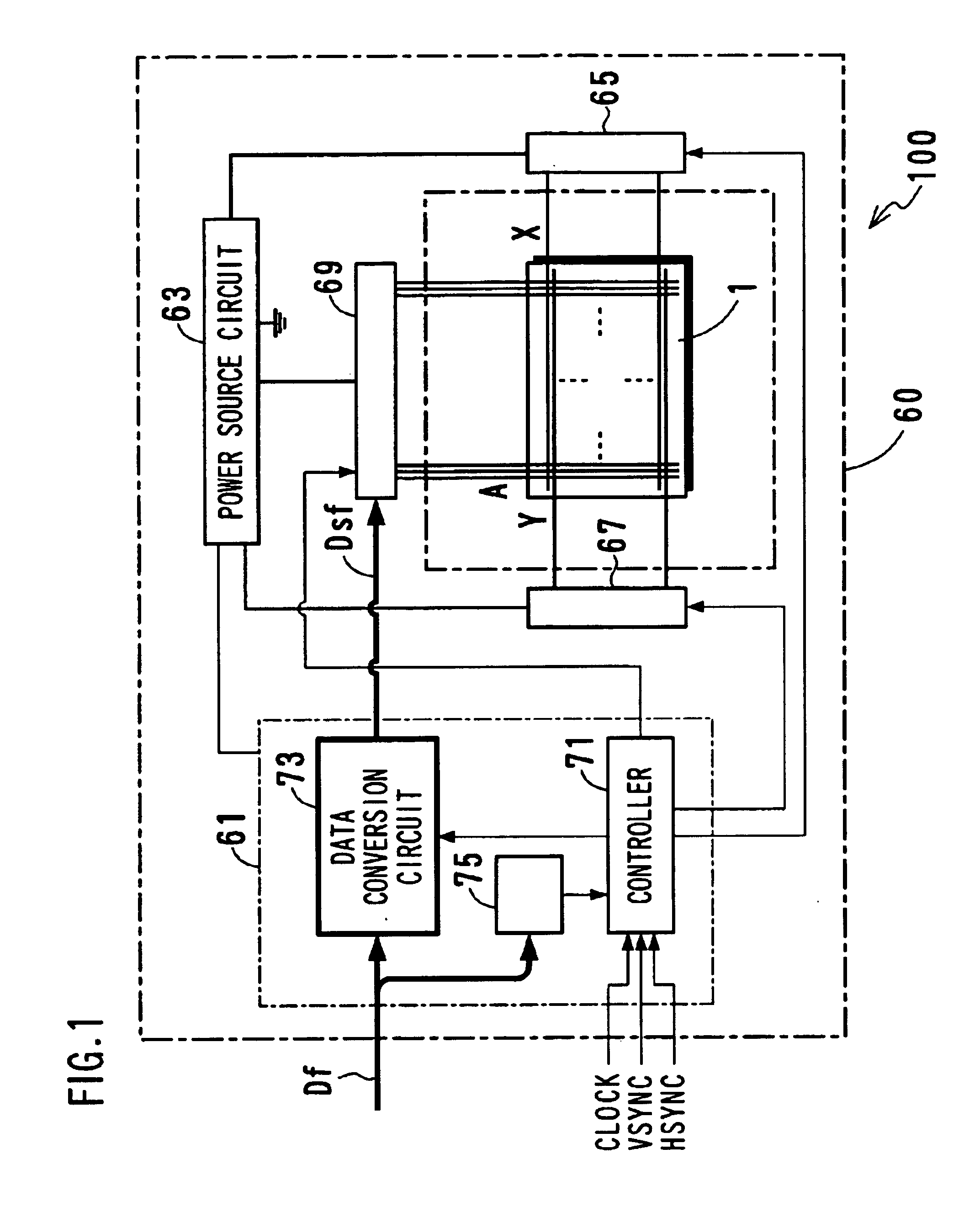
[0026]FIG. 1 shows a structure of a display device according to a first embodiment. The display device 100 comprises a surface discharge type PDP 1 having a screen of m columns and n rows, and a drive unit 60 for lighting m×n cells selectively. The display device 100 is used as a wall-hung television set or a monitor of a computer system.

[0027]PDP 1 includes display electrodes X and Y arranged in parallel for generating display discharge, and address electrodes A arranged so as to cross the display electrodes. The display electrodes X and Y extend in the row direction of the screen (in the horizontal direction), and the display electrode Y is used as a scan electrode for selecting a row upon addressing. The address electrode A extends in the column direction (in the vertical direction) and is used as a data electrode for selecting a column. A color arrangement of the color display has a stripe pattern in which red, green and blue colors are disposed alternate...

second embodiment

[0036][Second Embodiment]

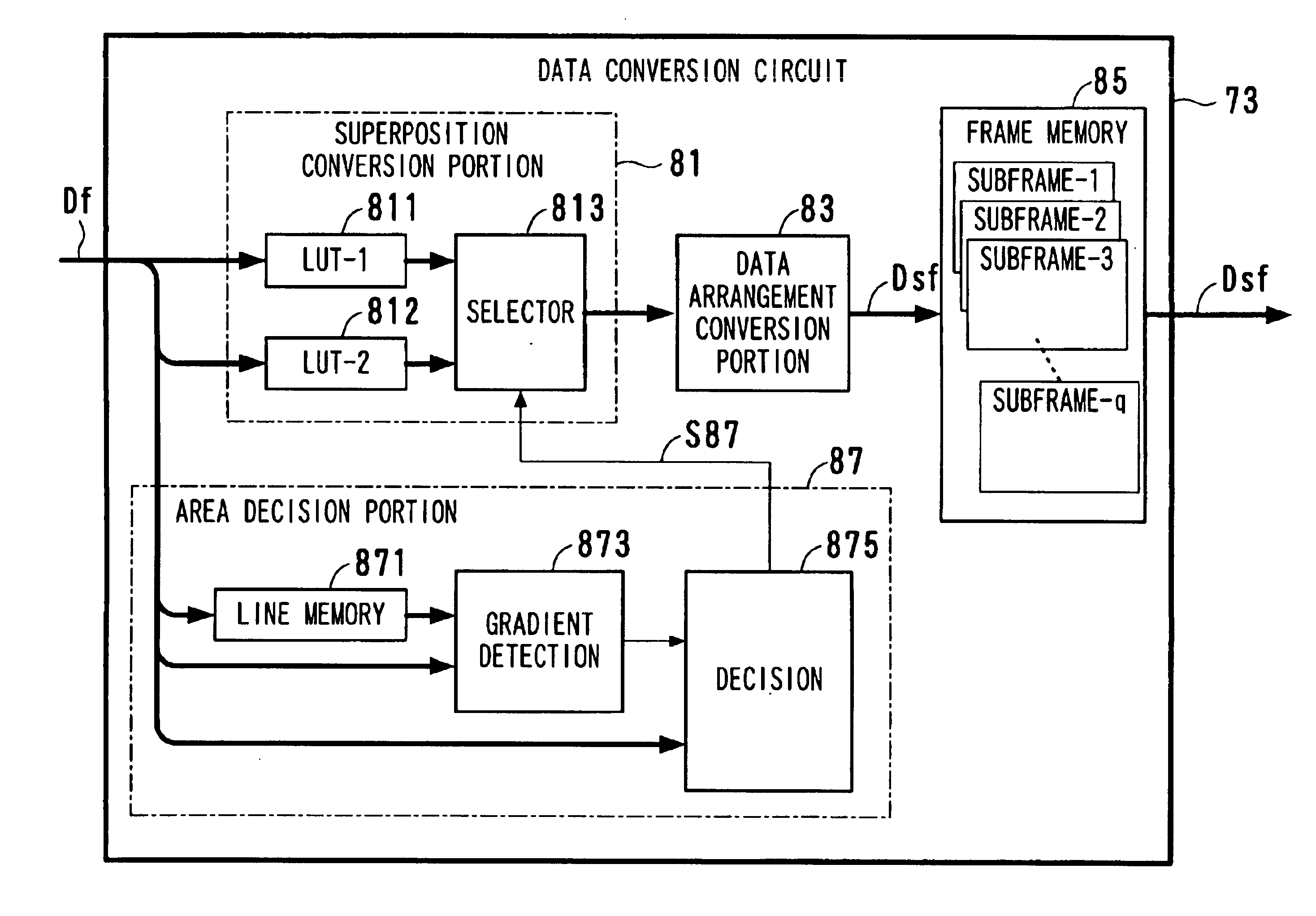
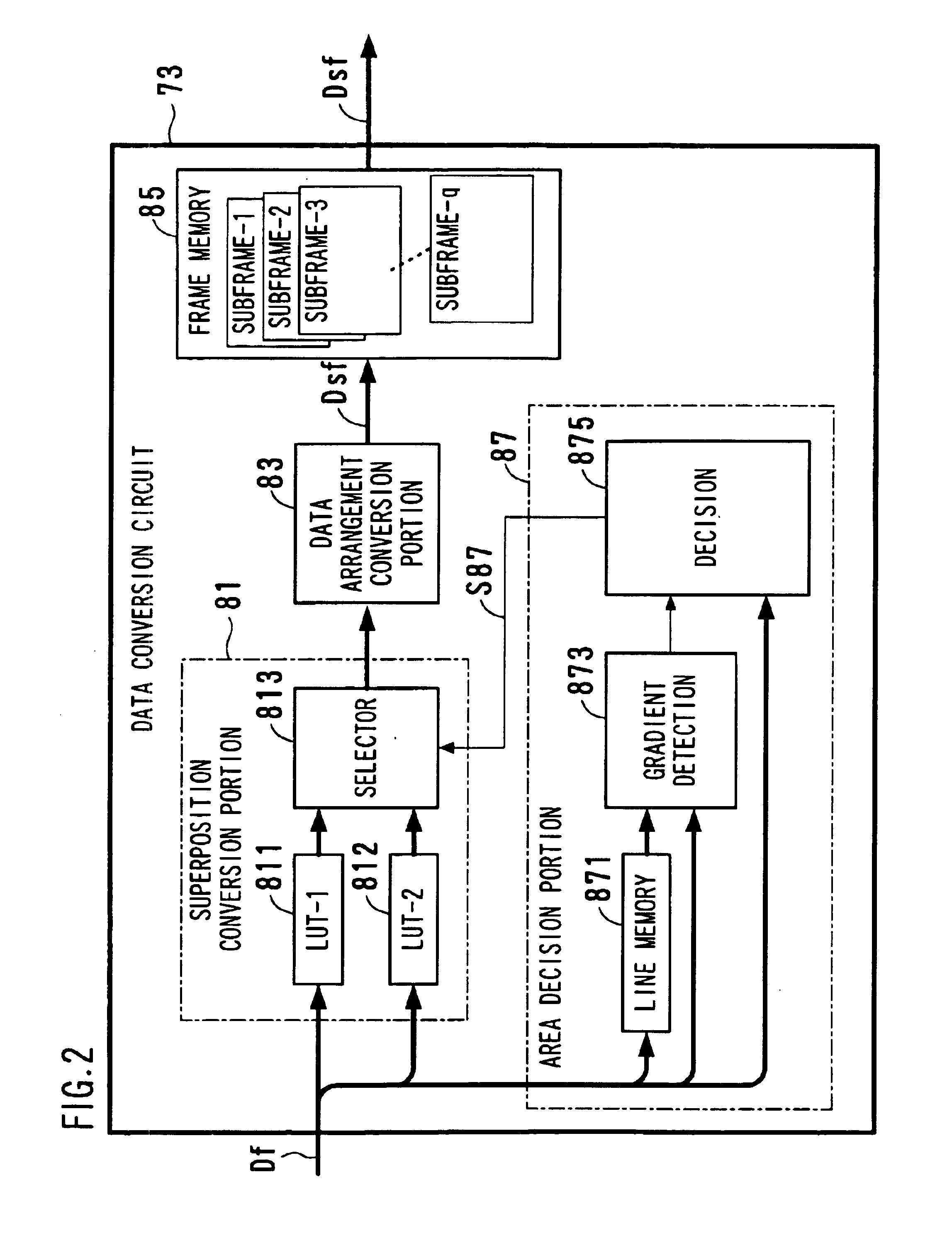
[0037]In a second embodiment, the area decision circuit shown in FIG. 2 is modified as follows.

[0038]FIG. 6 is a block diagram showing an area decision portion according to the second embodiment. The area decision portion 88 includes a line memory 881, a gradient detection circuit 883, a decision circuit 885, a frame memory 886 and a movement detection circuit 887. Functions of the line memory 881 and the gradient detection circuit 883 are the same as in the first embodiment.

[0039]The area decision portion 88, which performs a decision in accordance with the gradation and the luminance gradient, also decides whether the noted pixel is contained in an image of a moving object. Even if the noted portion in the display screen has a specific gradation, a dynamic pseudo contour can be recognized actually by human eyes only when the portion is moving and the observer is tracing the portion. The movement detection circuit 887 compares a frame transferred directly f...


PUM


Abstract

A method for driving a plasma display panel is provided in which dynamic pseudo contours are reduced and pattern noises are suppressed so that image quality of an animation display is improved. In the method, a superposition method is applied only to the area of a display image, which is made of pixels having a gradation at which only one of plural subframes having the same luminance weight concerning the superposition method is lighted and has a luminance gradient within a preset value range between the neighboring pixels.

Description

BACKGROUND OF THE INVENTION[0001]1. Field of the Invention[0002]The present invention relates to a method and a device for driving an AC type plasma display panel.[0003]A plasma display panel (PDP) has two features of high speed and high resolution that are suitable for television sets and computer monitors. A PDP is used for a large screen display device. One of tasks about a PDP is to reduce a pseudo contour of an animation display.[0004]2. Description of the Prior Art[0005]For a gradation display using a PDP, a method is widely used that comprises the steps of replacing one frame with a plurality of subframes having weights of luminance, and setting on and off of light emission of each cell of a subframe. For example, cells are lighted only in subframes having weight 1 for gradation 1 and are lighted in subframes having weight 2 and in subframes having weight 8 for gradation 10, so that each of gradation levels corresponds to a combination of subframes to be lighted (this is call...

Claims


Application Information

Patent Timeline
IPC IPC(8): G09G3/28G09G3/20H04N5/66G09G3/288G09G3/298
CPCG09G3/2029G09G3/2051G09G3/2803G09G2320/0261G09G2320/0266G09G2320/106G09G3/291G09G3/296
Inventor AWAMOTO, KENJITAKAYAMA, KUNIO
Owner HITACHI PLASMA PATENT LICENSING
Learn More