Signal generation circuit, frequency measurement device including the signal generation circuit, and signal generation method

Active Publication Date: 2011-04-14
SEIKO EPSON CORP
View PDF106 Cites 18 Cited by
  • Summary
  • Abstract
  • Description
  • Claims
  • Application Information

AI Technical Summary

Benefits of technology

[0008]In accordance with an advantage of some aspects of the invention, it is possible to provide a frequency change measuring device with an improved frequency measurement resolving power using a relatively si

Problems solved by technology

As errors that could occur at the time of measurement, plus/minus 1 count errors and errors caused by jitter at trigger level could occur, and in addition, errors that originate from the oscillation stability of the quartz oscillators would be superposed on

Method used


Image

  • Signal generation circuit, frequency measurement device including the signal generation circuit, and signal generation method
  • Signal generation circuit, frequency measurement device including the signal generation circuit, and signal generation method
  • Signal generation circuit, frequency measurement device including the signal generation circuit, and signal generation method

Examples


embodiment 1

[0065]4. Embodiment 1[0066](1) Exemplary Structure of Frequency Measurement Device[0067](2) Exemplary Structure of Variable Rate Frequency Divider[0068](3) Exemplary Operation of Variable Rate Frequency Divider[0069](4) Exemplary Operation of Frequency Measurement Device

embodiment 2

[0070]5. Embodiment 2[0071](1) Exemplary Structure of Frequency Measurement Device[0072](2) Exemplary Structure of Variable Rate Frequency Divider[0073](3) Exemplary Operation of Variable Rate Frequency Divider

[0074]6. Conclusion

[0075]7. Supplement

[0076]1. Definition

[0077]First, terms used in this specification are defined as follows.

[0078]An “OO section” and an “OO circuit” (OO may be any arbitrary words)” include an electrical section and an electrical circuit without any particular limitation thereto, respectively, and may also include a physical mean that achieves the function of the circuit or the section or a functional mean that is realized by software, Also, the function of one circuit or one section may be each realized by two or more physical means or functional means, or the function of two or more circuits or sections may be realized by one physical mean or one functional mean.

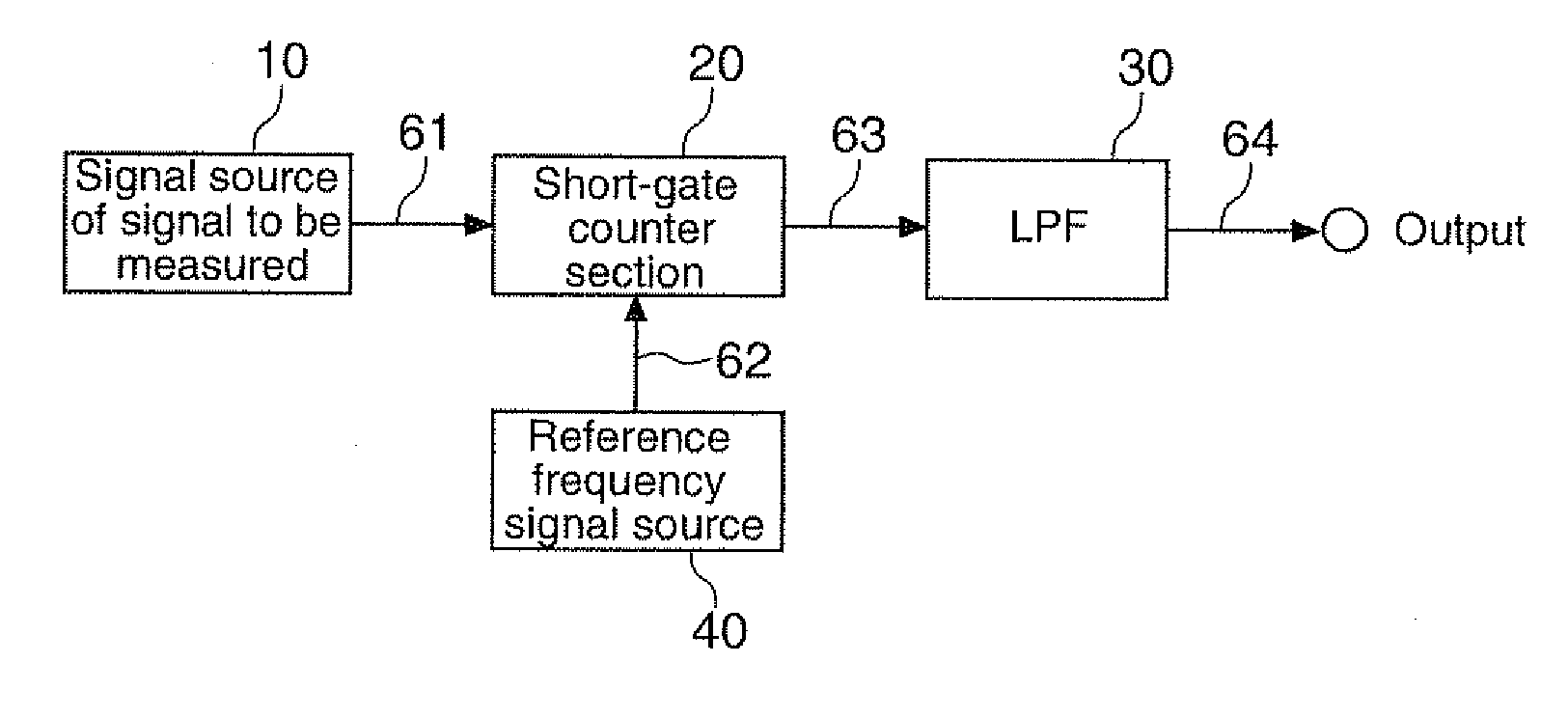
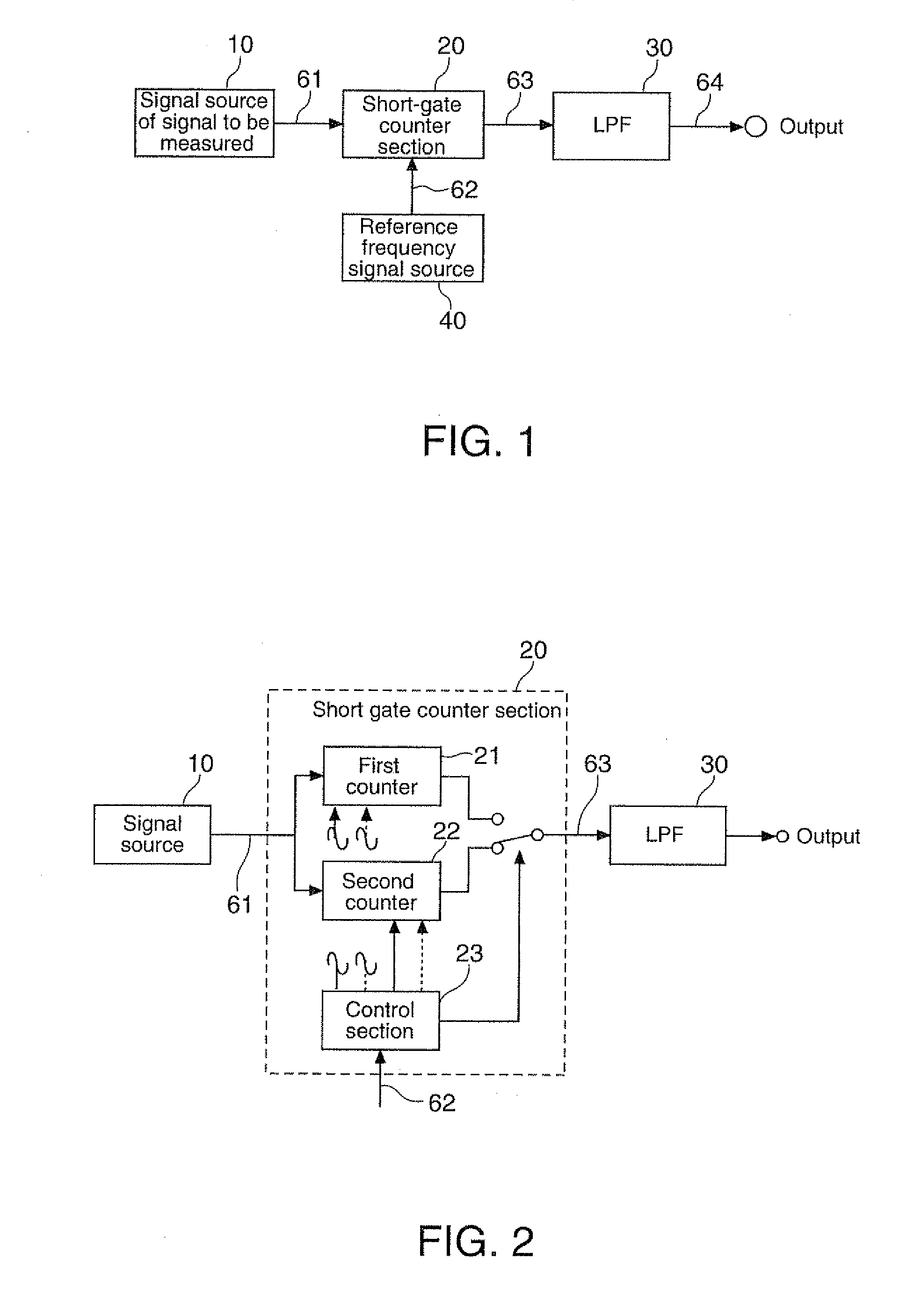
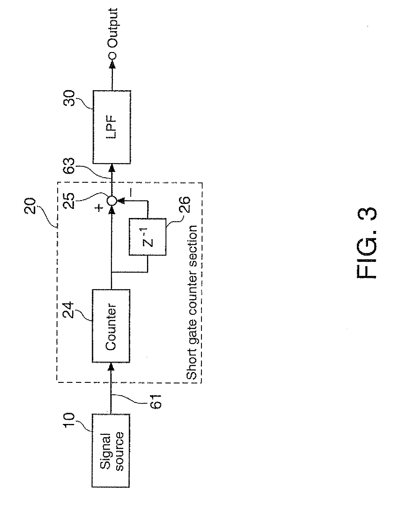
[0079]2. Summary of Frequency Measurement Device that uses Short-Gate Time Count Method

[0080]FI...

embodiment example 1

4. Embodiment Example 1

[0135]Hereinbelow, referring to FIGS. 19 through 26, Embodiment 1 in accordance with an embodiment of the invention will be described.

[0136](1) Exemplary Structure of Frequency Measurement Device

[0137]FIG. 19 is a diagram of a first exemplary structure of a frequency measurement device equipped with a variable rate frequency divider section 50. As shown in FIG. 19, the frequency measurement device is structured with a signal source of signal to be measured 10, a reference frequency signal source 40, a variable rate frequency divider section 50, a short gate counter section 20, and a low-pass filter 30. It is noted here that the signal source of signal to be measured 10, the short gate counter section 20 and the low-pass filter 30 have basically the same structure and function as those of the frequency measurement device described above with reference to FIG. 1, and therefore their description is omitted.

[0138]Reference Frequency Signal Source 40

[0139]The refer...


PUM


Abstract

A signal generation circuit includes: a first signal source that generates a first signal; and a variable rate frequency divider section that generates a variable rate frequency-divided signal in which a first frequency-divided signal obtained by frequency-dividing the first signal by a first frequency dividing ratio and a second frequency-divided signal obtained by frequency-dividing the first signal by a second frequency dividing ratio temporally alternately appear in a specified mixing ratio.

Description

[0001]The present application claims a priority based on Japanese Patent Application No. 2009-234514 filed on Oct. 8, 2009, the contents of which are incorporated herein by reference.BACKGROUND[0002]1. Technical Field[0003]The invention relates to measurement of frequency and, more particularly, to devices capable of detecting very small changes in frequency, and signal generation circuits and signal generation methods that can be used for the devices.[0004]2. Related Art[0005]As frequency measurement systems, a direct count system and a reciprocal system are known. According to the direct count system, pulses passing within a predetermined gate time are counted (see, for example, Japanese laid-open patent application JP-A-2001-119291). According to the reciprocal system, a pulse period is accurately measured, and a frequency is obtained from its time reciprocal (see, for example, Japanese laid-open patent application JP-A-5-172861). The direct count system may be realized with a re...

Claims


Application Information

Patent Timeline
IPC IPC(8): G01R23/00H03B19/00
CPCG01R23/10
Inventor TODOROKIHARA, MASAYOSHI
Owner SEIKO EPSON CORP
Why Eureka
Try Eureka