Air bag with pressure-managed gas delivery inflatable duct

a technology of airbags and inflatable ducts, which is applied in the direction of pedestrian/occupant safety arrangements, vehicular safety arrangments, vehicle components, etc., can solve the problems of difficult to obtain the high pressure required for the pelvis portion of the airbag, and the potential for backflow

Active Publication Date: 2013-12-03
AUTOLIV ASP INC
View PDF27 Cites 24 Cited by
  • Summary
  • Abstract
  • Description
  • Claims
  • Application Information

AI Technical Summary

Problems solved by technology

However, as the required pressure differential grows, there exists the potential for backflow wherein the inflation gas contained in the high-pressure chamber flows back into the low-pressure chamber by way of the fluid communication provided within the diffuser.
As a result, it is difficult to obtain the high pressures required for the pelvis portion of the airbag while simultaneous inflating the thorax portion of the airbag to a low pressure.

Method used


Image

  • Air bag with pressure-managed gas delivery inflatable duct
  • Air bag with pressure-managed gas delivery inflatable duct
  • Air bag with pressure-managed gas delivery inflatable duct

Examples


Embodiment Construction

[0020]The presently preferred embodiments of the present invention will be best understood by reference to the drawings, wherein like parts are designated by like numerals throughout. It will be readily understood that the components of the present invention, as generally described and illustrated in the figures herein, could be arranged and designed in a wide variety of different configurations. Thus, the following more detailed description of the embodiments of the present invention, as represented in the figures, is not intended to limit the scope of the invention, as claimed, but is merely representative of presently preferred embodiments of the invention.

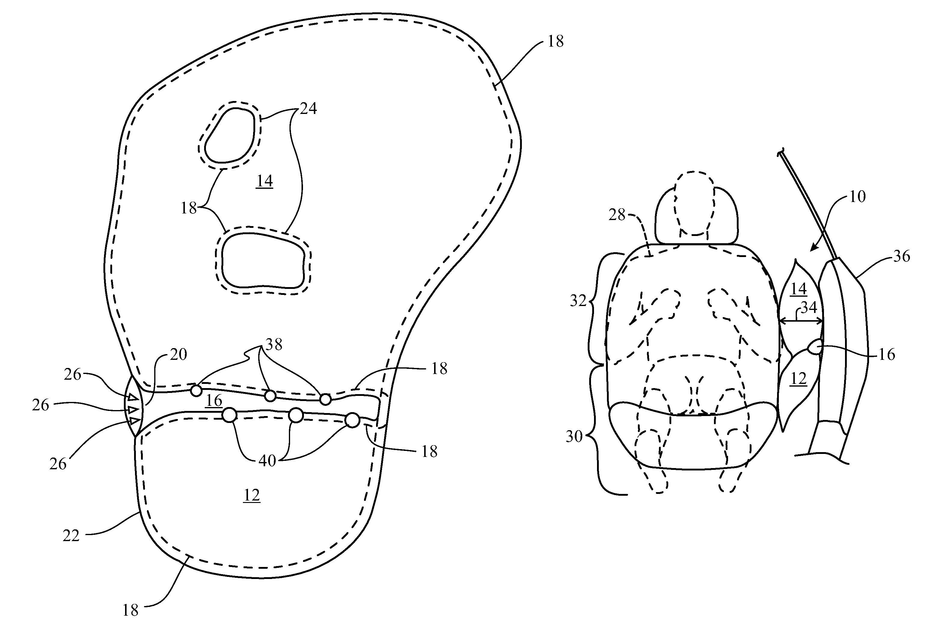
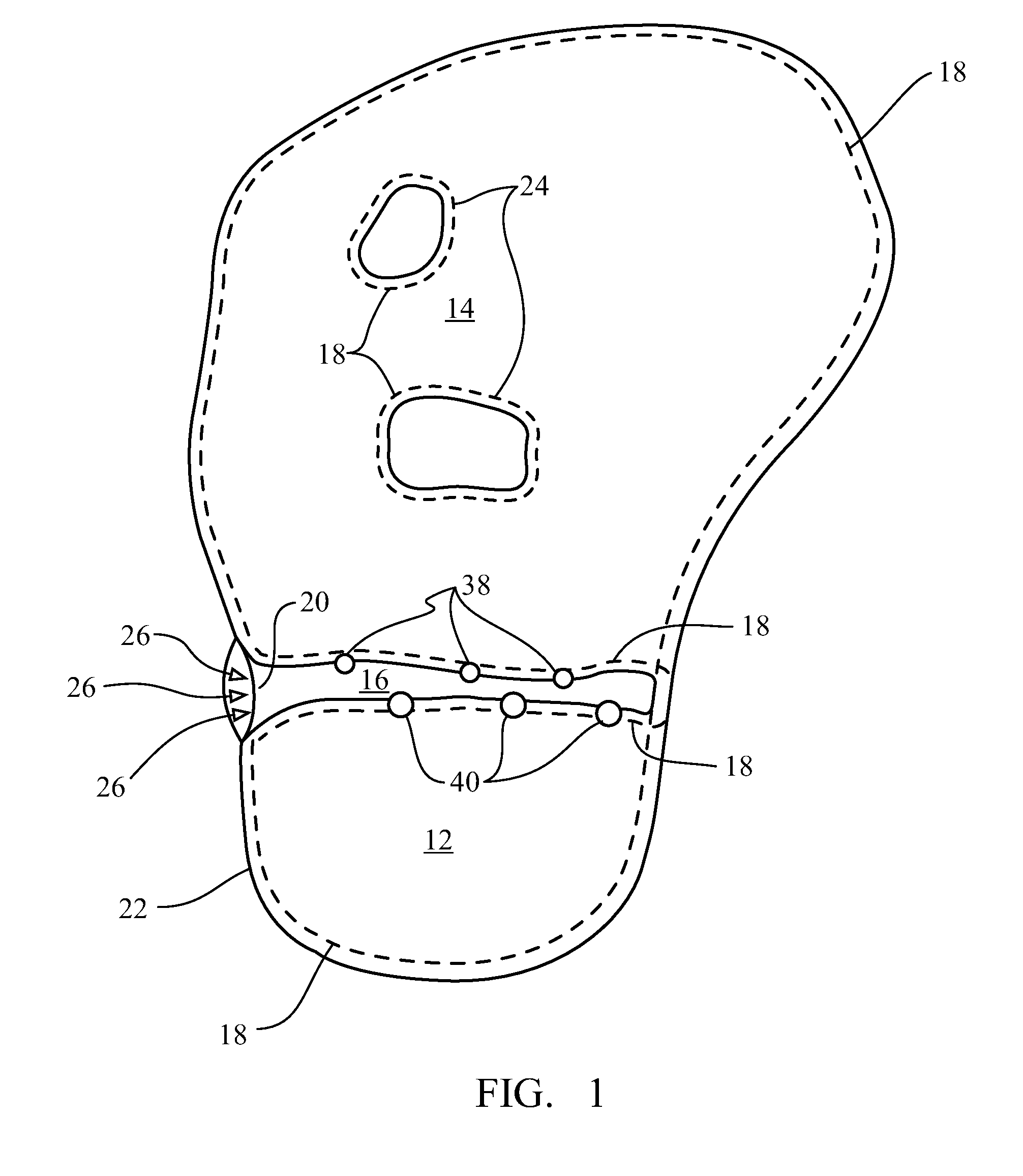
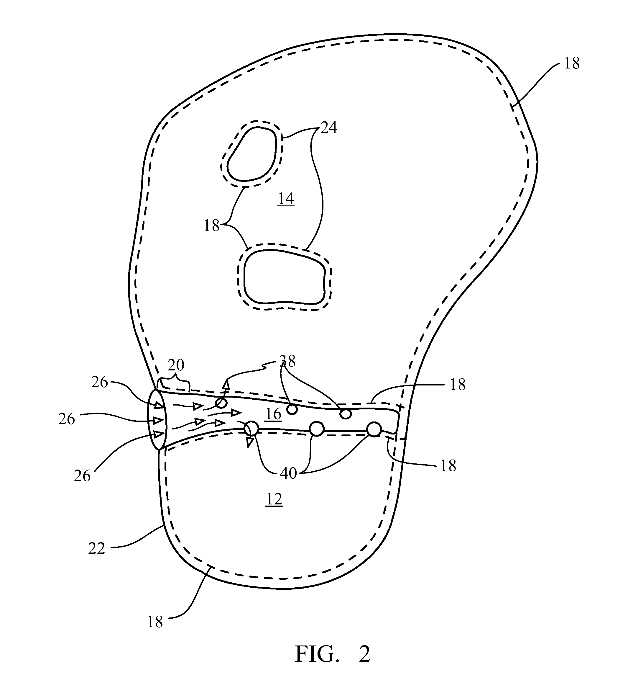
[0021]Referring now to FIG. 1, an inflatable air bag 10 according to the present embodiments is illustrated. The inflatable air bag 10 shown in FIG. 1 is formed by sheets of material having stitching 18 at the inflatable air bag perimeter 22. Stitching 18 around the perimeter 22 forms chambers 12 and 14 between the sheets of fa...


PUM


Abstract

An inflatable side airbag has an inflatable duct for the delivery of inflation gas. The inflatable duct of the inflatable side airbag provides for rapid deployment of a multi-chamber air bag while controlling the rate of inflation and the relative pressure of the chambers. The inflatable duct allows a single inflator to inflate a high pressure pelvis chamber and a lower pressure thorax chamber while preventing fluid communication between the two chambers upon completion of inflation.

Description

BACKGROUND OF THE INVENTION[0001]Airbags and airbag systems are known in the art and are now standard on motor vehicles. These airbag systems generally are designed such that in the event of an accident or a crash, an inflatable airbag will become positioned between a vehicle occupant and an interior object or surface and will prevent the vehicle occupant from harmful impact with a portion of the vehicle interior. As is known in the art, airbags are currently added to the vehicle's steering wheel, dashboard, and / or at other locations within the vehicle. The inclusion of these airbag systems within motor vehicles have been credited with saving many lives and preventing many injuries.[0002]Many typical airbag systems comprise several individual components joined to form an operational module. Such components generally include an airbag cushion, an airbag inflator, a sensor, and an electronic control unit. Airbag cushions are typically made of a thin, durable fabric that is folded to f...

Claims


Application Information

Patent Timeline
Patent Type & Authority Patents(United States)
IPC IPC(8): B60R21/207B60R21/21B60R21/26B60R21/262B60R21/231B60R21/233
CPCB60R21/23138B60R21/233B60R21/2346B60R21/239B60R2021/0044B60R2021/0055B60R2021/23316B60R2021/23324B60R2021/23382
Inventor RAVENBERG, MIKESHANKAR, BALASKANDANJAMISON, PATRICKYAKUMO, ARTHURLUNT, LARRY F.
Owner AUTOLIV ASP INC
Why Eureka
Try Eureka