Method and Installation for the Production of Containers

a container and installation method technology, applied in the field of containers, can solve the problems of insufficient heat transfer speed, insufficient efficiency of container complex shapes, and negative impact on production rates, so as to achieve effective cooling and increase production rates

Inactive Publication Date: 2007-10-11
SIDEL PARTICIPATIONS SAS
View PDF7 Cites 22 Cited by
  • Summary
  • Abstract
  • Description
  • Claims
  • Application Information

AI Technical Summary

Benefits of technology

[0014] The invention is aimed particularly at overcoming the aforementioned disadvantages by providing a method and an installation for the production of containers whereby the containers can be cooled effectively in a simple and economic manner and whereby in fine the production rates can be increased.

Problems solved by technology

This situation particularly affects the base of the containers, which is generally thicker than their body and, therefore, tends to cool more slowly than the body and to remain momentarily soft on leaving the forming unit.
While this method is satisfactory for containers of simple shape, offering few obstacles to the flow of air or gas, its effectiveness nevertheless proves insufficient for containers having complex shapes, such as bottles with a petaloid base.
In this instance, the heat transfer is not quick enough to prevent even minimal deformation of the base.
This slow cooling progress negatively impacts the production rates.
Firstly, the mist proves difficult to direct, which means that the whole of the containers, and not just the unstable areas, are sprayed.
This results in an insufficient efficiency of the cooling unit, which is particularly manifested by excess water consumption.
Secondly, the water which has not been vaporized on contact with the hot areas of the container tends to be deposited and to accumulate in areas from which it has to be drained.

Method used


Image

  • Method and Installation for the Production of Containers
  • Method and Installation for the Production of Containers
  • Method and Installation for the Production of Containers

Examples


Embodiment Construction

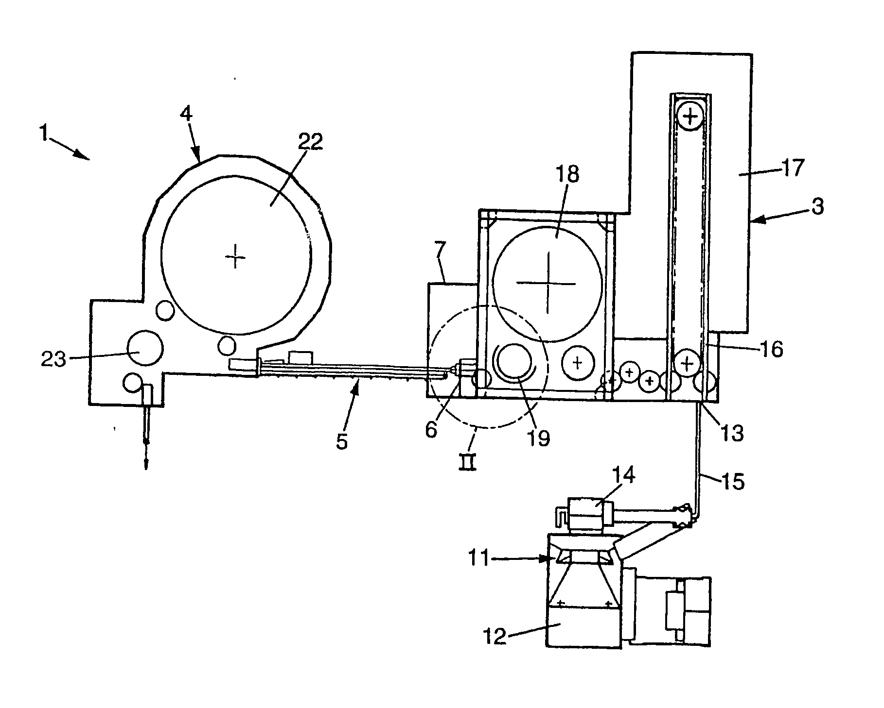
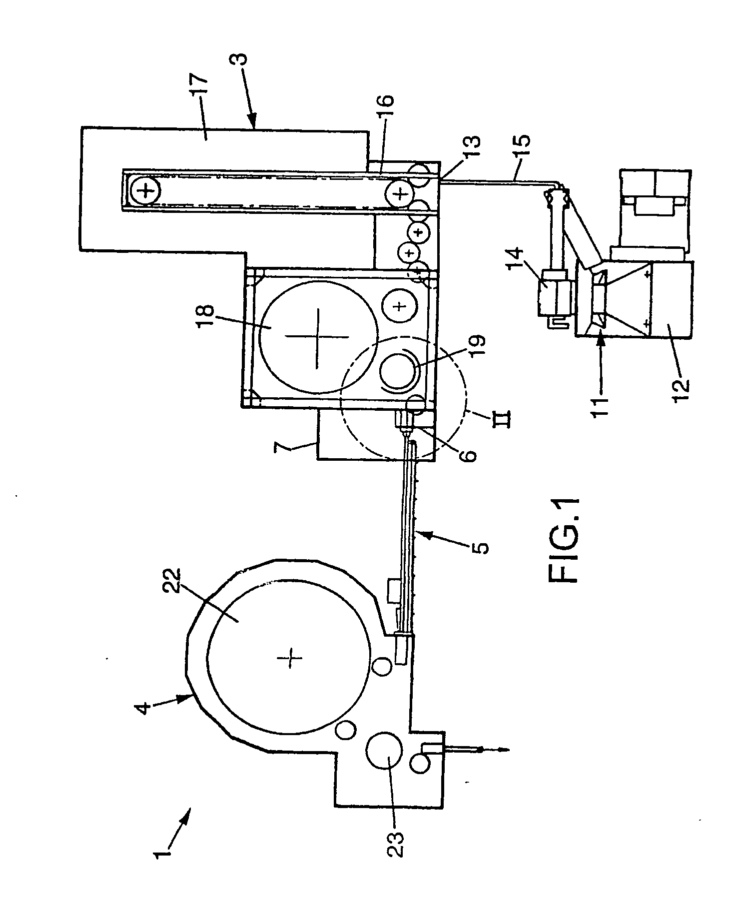
[0033]FIG. 1 shows an installation 1 for the production of containers 2 such as bottles, starting from thermoplastic preforms.

[0034] The installation 1 comprises a forming unit 3 to form the containers 2, a filling unit 4 to fill the containers 2, a conveyor 5 for conveying the formed containers 2 from the outlet 6 of the forming unit 3 toward the filling unit 4, and a cooling unit 7 placed at the outlet 6 of the forming unit 3 along the path of the containers 2 formed by the conveyor 5.

[0035] The containers 2 are made for example of polyethylene terephthalate (PET), polyethylene naphthalate (PEN), or any other suitable thermoplastic. Once formed, each container 2 has a body 8 (which may be cylindrical), a neck 9 and, at the opposite end to the neck 9, a base 10.

[0036] The installation 1 additionally comprises a supply unit 11 which delivers the preforms to the forming unit 3. The supply unit 11 comprises, for example, a hopper 12 in which the preforms, prefabricated by injection...


PUM

PropertyMeasurementUnit
relative pressureaaaaaaaaaa
temperatureaaaaaaaaaa

Abstract

A method of producing containers, including a forming step in which thermoplastic performs are used to form containers including a body and a base; and, subsequently, a cooling step in which the formed containers are cooled by projecting a jet onto the containers in a localized manner on a target area including the base thereof, the jet consisting of a mixture of a gas and an atomized liquid which are both at a relative pressure of less than approximately 1 bar. The invention also relates to an installation for the production of containers, which is adapted for the aforementioned method.

Description

FIELD OF THE INVENTION [0001] The invention is concerned with the production of containers. [0002] It relates more particularly to a method, and also to an installation, for the production of containers—particularly bottles—from thermoplastic preforms. BACKGROUND OF THE INVENTION [0003] Such a method generally comprises a first step during which the preforms are heated as they file through a tunnel oven, followed by a second step, for the actual forming operation, during which the hot preforms are introduced into a blow molding or stretch blow molding device so as to be shaped into containers. The step of heating the preforms consists in bringing the thermo-plastic which constitutes them, or at the very least the temperature of the thermoplastic of their areas which are to be modified to obtain the containers, to a temperature exceeding the glass transition temperature, that is to say the softening temperature of said material. Thus, by way of example, when the containers to be prod...

Claims


Application Information

Patent Timeline
Patent Type & Authority Applications(United States)
IPC IPC(8): B29C49/64B29C49/06B29C49/66B29C49/78
CPCB29C49/06B29C49/64B29L2031/7158B29C49/78B29K2067/00B29C49/66B29C35/16B29C2035/1691B29C2949/0715
Inventor TROUILLET, MICKAEL
Owner SIDEL PARTICIPATIONS SAS
Why Eureka
Try Eureka