Water/fluids surge/backflow protection systems and management

a technology of protection system and water flow, applied in the direction of machines/engines, liquid fuel engines, sewage draining, etc., can solve the problems of high tide surge, severe damage to property, loss of life,

Inactive Publication Date: 2013-12-10
HUBBELL JR PAUL J
View PDF15 Cites 3 Cited by
  • Summary
  • Abstract
  • Description
  • Claims
  • Application Information

AI Technical Summary

Benefits of technology

[0010]A second object of the present invention is to provide a pumping station that can discharge storm waters into a receiving body at two different vertical elevations, where the selected discharge elevation is activated by operating a by-pass valve which is remotely controlled.
[0011]A third object of the present invention is to provide a pumping station that can discharge storm waters into two different discharge outlets by using a by-pass valve, where one discharge outlet is a receiving body such as a river, lake, bay, etc., and the second discharge feeds the storm water into an underground aquifer.

Problems solved by technology

This inability arises when there is excessive rainfall producing flooding within the protected area and where the water level in the discharge bodies is unusually high as the result high tides and storm surges.
These same areas are subject to encounter severe hurricane weather events that are known to produce high tidal surges along the bays and estuaries that receive the discharged storm waters from the pumping stations.
Failure of the pumping stations to adequately remove the accumulated storm waters from the levee-protected land areas has been known to result in loss of life and severe damage to property.

Method used


Image

  • Water/fluids surge/backflow protection systems and management
  • Water/fluids surge/backflow protection systems and management
  • Water/fluids surge/backflow protection systems and management

Examples


Embodiment Construction

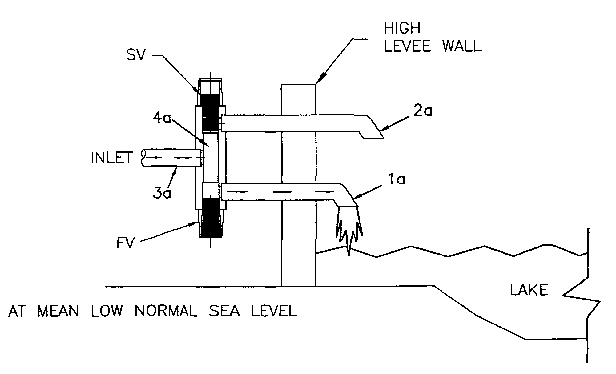
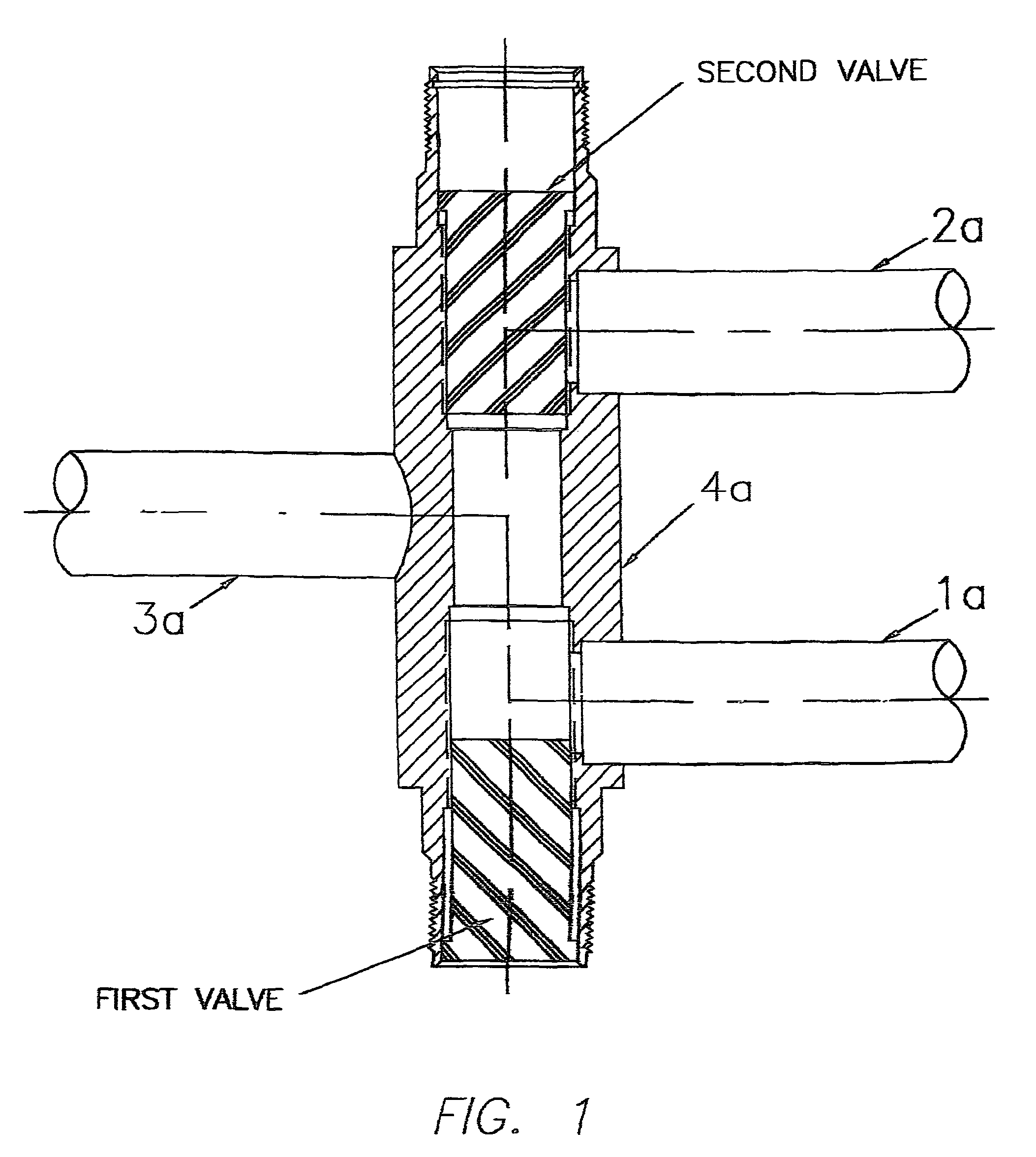
[0018]FIG. 1 illustrates a valve design of the type useful for implementing the objectives of this invention. It consists of a main manifold body 4a, with an internal chamber capable of communicating with discharge pipes 1a and 2a. A pump discharge pipe 3a also communicates with the internal chamber. The first valve, located at the bottom of FIG. 1, is normally open (back-seated) to the passageway chamber of manifold 4a which allows flow from the inlet 3a pump discharge pipe through outlet piping 1a into a waterway; the second valve, located at the top of FIG. 1, is closed (front-seated) to the outlet pipe 2a, thus preventing flow through outlet pipe 2a. This configuration is used for normal operation of the pumping station.

[0019]The valve system of FIG. 1 is operated by driving the first valve element up to block the flow through discharge port 1a, i.e., front-seating the first valve, while concurrently driving the second valve up to allow flow through discharge pipe 2a, i.e., back...


PUM


Abstract

This design addresses the problems in areas below sea level adjacent to coastal communities with shallow canals / inlets with high tides / surges entering the discharge piping outlets arranged for normal average mean sea levels from pumping stations with outflow into a reservoir / body i.e., lake, river or waterway that is affected during storms, hurricanes or heavy rains driven by winds and high tides that render pumping inefficient at least and / or inoperable at worst. Included in this design is an inlet of a manifold connected to the pump's discharge, a normal discharge outlet and a second optional bypass discharge piping outlet, elevated over or through a high wall. Also included is automatic / manual shutoff valves and variable speed drive motor. The bypass discharge outlet includes, prior to the distal end, an ancillary piping arrangement that allows portions of the discharge flow directed back into underground aquifers for water table replenishment to aid subsidence maintenance.

Description

REFERENCE TO RELATED DISCLOSURE[0001]The present application includes and refers to the Provisional Patent Application No. 61 / 199,428 filed on Nov. 18, 2008; titled Water / Fluids Surge / Backflow Protection System And Methods.TECHNICAL FIELD[0002]The present invention initially relates to the existing designs and methods of operation and maintenance of pumping stations that attempt to regulate and control the discharge and outflow of drainage systems water collection caused by rainfall, tropical storms and / or hurricanes, to the interior lands within the levee protection system.BACKGROUND ART[0003]Pumping stations are used to drain storm waters from low lying land areas contained within a protective levee system and deposit those storm waters into lakes, bays, reservoirs, rivers, etc. outside of the protected levee system. Those waters outside of the levee protection system are usually subject to tidal fluctuations as well as storm surges. Most existing pumping stations in low elevation...

Claims


Application Information

Patent Timeline
Patent Type & Authority Patents(United States)
IPC IPC(8): E02B8/04
CPCE03F1/002E03F5/107F04D29/426F04D29/528Y10T137/87877
Inventor HUBBELL, JR., PAUL J.
Owner HUBBELL JR PAUL J
Why Eureka
Try Eureka