Check patentability & draft patents in minutes with Patsnap Eureka AI!

High frequency horn having a tuned resonant cavity

Active Publication Date: 2013-12-17
HARMAN INT IND INC
View PDF11 Cites 53 Cited by
  • Summary
  • Abstract
  • Description
  • Claims
  • Application Information

AI Technical Summary

Benefits of technology

The patent describes a high frequency horn used in a loudspeaker system that has two types of speakers. The high frequency horn has a chamber, mouth, and throat, and a connection to both a midrange transducer and a high frequency transducer. The design of the horn reduces issues with the output of the high-frequency speakers and also helps control the sound produced by the midrange speakers. Overall, this design improves the quality of sound produced by the loudspeaker system.

Problems solved by technology

Unfortunately, the formation of these acoustical standing waves result in “dips” in the far-field midrange frequency response of the combined output sound waves 224 due to acoustical cancelation at the frequencies where the “dips” occur.

Method used


Image

  • High frequency horn having a tuned resonant cavity
  • High frequency horn having a tuned resonant cavity
  • High frequency horn having a tuned resonant cavity

Examples


Embodiment Construction

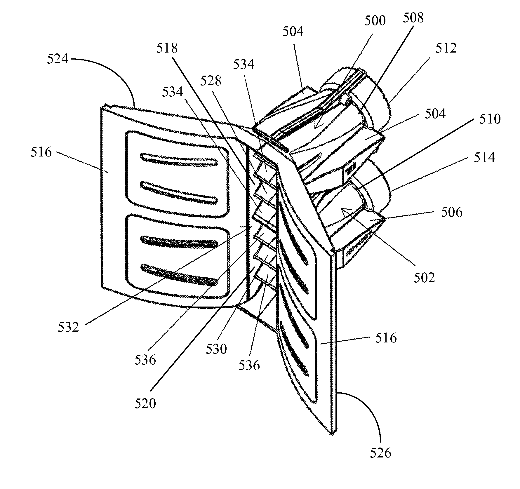
[0033]FIGS. 5 through 13 illustrate various implementations of a high frequency horn 500 of the invention. In FIG. 5, a perspective view of an example of an implementation of two high frequency horns 500 and 502 each utilizing a tuned resonate cavity 504 and 506, respectively, (also referred to interchangeably as “tuned resonate chambers 504 and 506”) is shown. The high frequency horns 500 and 502 utilize a horn design that includes a horn throat 508 and 510 each connected to the high frequency transducer 512 and 514 (also referred to interchangeably as “high frequency drivers 508 and 510”), on one end, and a horn mouth 518 and 520 connected to opposing horn flares 516 at the opposite end of the high frequency horn 500 and 502, respectively, where the horn flares 516 may be sound integrators (which are described in U.S. Pat. Nos. 7,134,523 and 7,324,654). The hollow taper tube sections in the high frequency horn 500 and 502 are known as horn chambers which extend between each horn t...


PUM


Abstract

A high frequency horn for use in a multiple frequency loudspeaker system having a midrange transducer and a high frequency transducer is disclosed. The high frequency horn includes a horn chamber, horn mouth, a horn throat, a tuned resonant cavity, and a port connected to both the tuned resonant cavity and the horn chamber. The horn throat and horn chamber are located on opposite sides of the horn chamber, the port is located proximate to the horn throat, and the horn throat is configured to be connected to the high frequency transducer. The tuned resonant cavity is tuned to reduce high frequency standing waves produced by the midrange transducer within the horn chamber.

Description

CROSS-REFERENCE TO RELATED APPLICATION[0001]This application claims priority under 35 U.S.C. 119(e) to U.S. Provisional Patent Application Ser. No. 61 / 381,923, titled “HORN HAVING A RESONATE CHAMBER TO CORRECT MID-RANGE FREQUENCY RESPONSE,” filed Sep. 10, 2010, which is herein incorporated by reference in its entirety.BACKGROUND OF THE INVENTION[0002]1. Field of the Invention[0003]This invention relates generally to loudspeakers, and in particular to a system for controlling the frequency response of a horn loudspeaker.[0004]2. Related Art[0005]In general multi-way loudspeaker systems are well known. Typical examples of multi-way loudspeaker systems include two-way loudspeakers and three-way loudspeakers. Generally, multi-way loudspeaker systems include multiple transducers (generally referred to as “loudspeakers,”“speakers,”“sound drivers,” or “drivers”) that operate at different frequency ranges. As an example, typical two-way loudspeakers include a low-frequency transducer and a ...

Claims


Application Information

Patent Timeline
IPC IPC(8): G10K11/02
CPCH04R1/26H04R1/2873H04R1/2865
Inventor WERNER, BERNARD M.
Owner HARMAN INT IND INC
Features
  • R&D
  • Intellectual Property
  • Life Sciences
  • Materials
  • Tech Scout
  • Unparalleled Data Quality
  • Higher Quality Content
  • 60% Fewer Hallucinations
Learn More