Waiting circuit

a waiting circuit and circuit technology, applied in the field of waiting circuits, can solve the problems of large size of demodulator, large amount of power to be consumed, and large amount of electric power consumption

Inactive Publication Date: 2000-07-04
HANGER SOLUTIONS LLC
View PDF1 Cites 104 Cited by
  • Summary
  • Abstract
  • Description
  • Claims
  • Application Information

AI Technical Summary

Problems solved by technology

A demodulator is large in size and consumes a lot of electric power.
This would cause a substantial amount of power to be consumed.

Method used


Image

  • Waiting circuit
  • Waiting circuit
  • Waiting circuit

Examples


Embodiment Construction

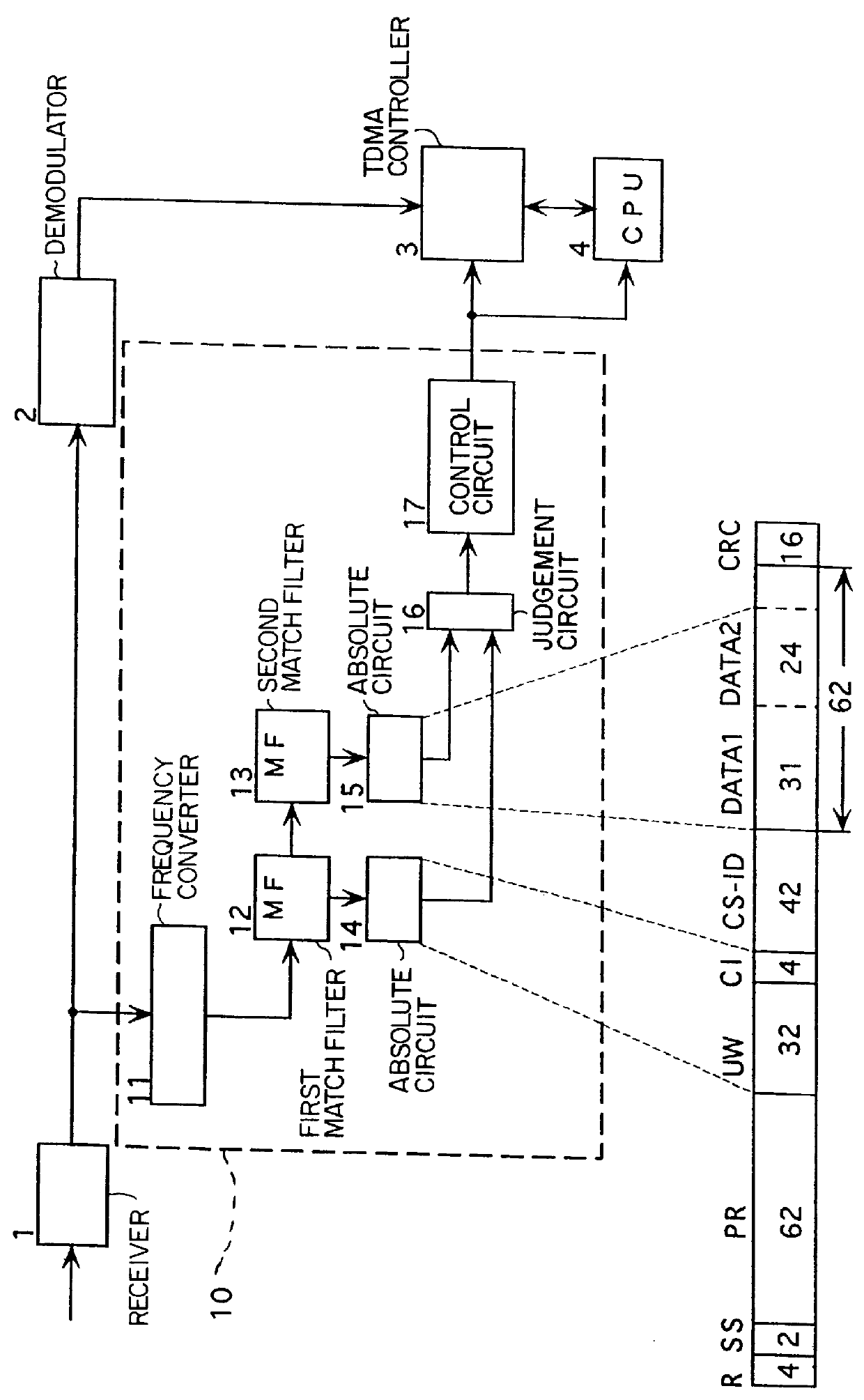
FIG. 1 is a block diagram showing a waiting circuit according to the present invention.

In FIG. 1, a portable terminal has a waiting circuit 10, a receiver 1 for converting a signal received by an antenna into a hard-limited intermediate frequency (IF) signal, a demodulator 2 for demodulating an output from the receiver 1, a TDMA controller 3 for receiving an output from the demodulator 2, and a CPU 4 for controlling the total circuits including the above TDMA controller 3. The intermediate frequency signal output from the receiver 1 is a square wave with a frequency of for example 10.8 MHz. The hard-limited IF signal is substantially a square wave of binary levels.

In the waiting circuit 10, the IF signal is input to a frequency converter 11 for converting the IF signal into a second intermediate frequency signal of a lower frequency such as 1.2 MHz. The first IF signal from the receiver is substantially a binary signal but may include high level bits of not sufficiently high levels....


PUM


Abstract

A waiting circuit which is utilized in a mobile communication system. The waiting circuit detects a predetermined signal from a base station. The waiting circuit starts other circuits in the mobile communication system which are in a sleep mode when the predetermined signal is received. The predetermined signal is generated in the base station. The predetermined signal has a speed equal to a predetermined symbol rate and is modulated to be an intermediate frequency signal. The intermediate frequency signal is sampled in response to a sampling clock that has a speed equal to an integer times the symbol rate. The sampled intermediate frequency signal is input to a match filter which multiplies the sample signal by a predetermined sequence of coefficients.

Description

1. Field of the InventionThe present invention relates to a waiting circuit for a portable terminal of a mobile and personal cellular system such as personal handy-phone system (PHS).2. Background of the InventionRecently, the use of a personal handy-phone system (PHS), the personal digital cellular (PDC) and other personal mobile and cellular systems have greatly expanded. A waiting reception mode is usually employed in order to decrease the electrical power consumption, because power consumption is one of the most important factors to consumers other than size and the light weight.The PHS system, uses a multi-carrier 4-time-slots-division-multiple-access (4-TDMA), a transfer manner of time-division-duplex (TDD) and a modulation manner of .pi. / 4 shift quadrature-phase-shift-keying (QPSK), so each of the users communicates through a time slot different from the other users' time-slots. When not in the communication mode, the portable terminal is set in a sleep-mode in which electric...

Claims


Application Information

Patent Timeline
Patent Type & Authority Patents(United States)
IPC IPC(8): H04B1/16H04M1/73H04M1/72H04Q7/32H04B1/26H04B7/26H04J1/00H04W52/02
CPCH04B1/1615H04W52/029Y02D30/70
Inventor ZHOU, CHANGMINGZHOU, XUPINGSHOU, GUOLIANG
Owner HANGER SOLUTIONS LLC
Why Eureka
Try Eureka