Systems and methods for receiving multiple input, multiple output signals for test and analysis of multiple-input, multiple-output systems

a technology of multiple inputs and output signals, applied in the field of systems and methods for receiving multiple inputs, multiple output signals for test and analysis of multiple inputs, multiple output systems, etc., can solve the problems of high cost of implementation, limiting the data throughput capacity of traditional use of multiple transmitters and receivers, and requiring multiple inputs

Inactive Publication Date: 2008-04-10
AGILENT TECH INC
View PDF14 Cites 107 Cited by
  • Summary
  • Abstract
  • Description
  • Claims
  • Application Information

AI Technical Summary

Benefits of technology

[0014]Various advantages, aspects and novel features of the present invention, as well as details of an illustrated implementation thereof, will be more fully understood from the following description and drawings.

Problems solved by technology

In the presence of high impairments in a challenging transmission environment, traditional use of multiple transmitters and receivers reaches a limit in data throughput capacity.
These massively parallel architectures are not without disadvantages.
Using one complete signal chain per input can be costly to implement.
Another disadvantage is that N complete instruments are difficult to accurately synchronize.
Lastly, use of N dedicated DSP processing chains slaved to N ADCs to extract the M data stream signals does not allow for much future flexibility as the emerging MIMO communication systems evolve.
Such solutions are not only expensive, they are further complicated by time, phase and trigger issues raised by the use of separate hardware to manage the channels.

Method used


Image

  • Systems and methods for receiving multiple input, multiple output signals for test and analysis of multiple-input, multiple-output systems
  • Systems and methods for receiving multiple input, multiple output signals for test and analysis of multiple-input, multiple-output systems
  • Systems and methods for receiving multiple input, multiple output signals for test and analysis of multiple-input, multiple-output systems

Examples


Embodiment Construction

[0028]In the following description of preferred implementations, reference is made to the accompanying drawings that form a part hereof, and which show, by way of illustration, specific implementations in which the invention may be practiced. Other implementations may be utilized and structural changes may be made without departing from the scope of the present invention.

MIMO Measuring Receiver

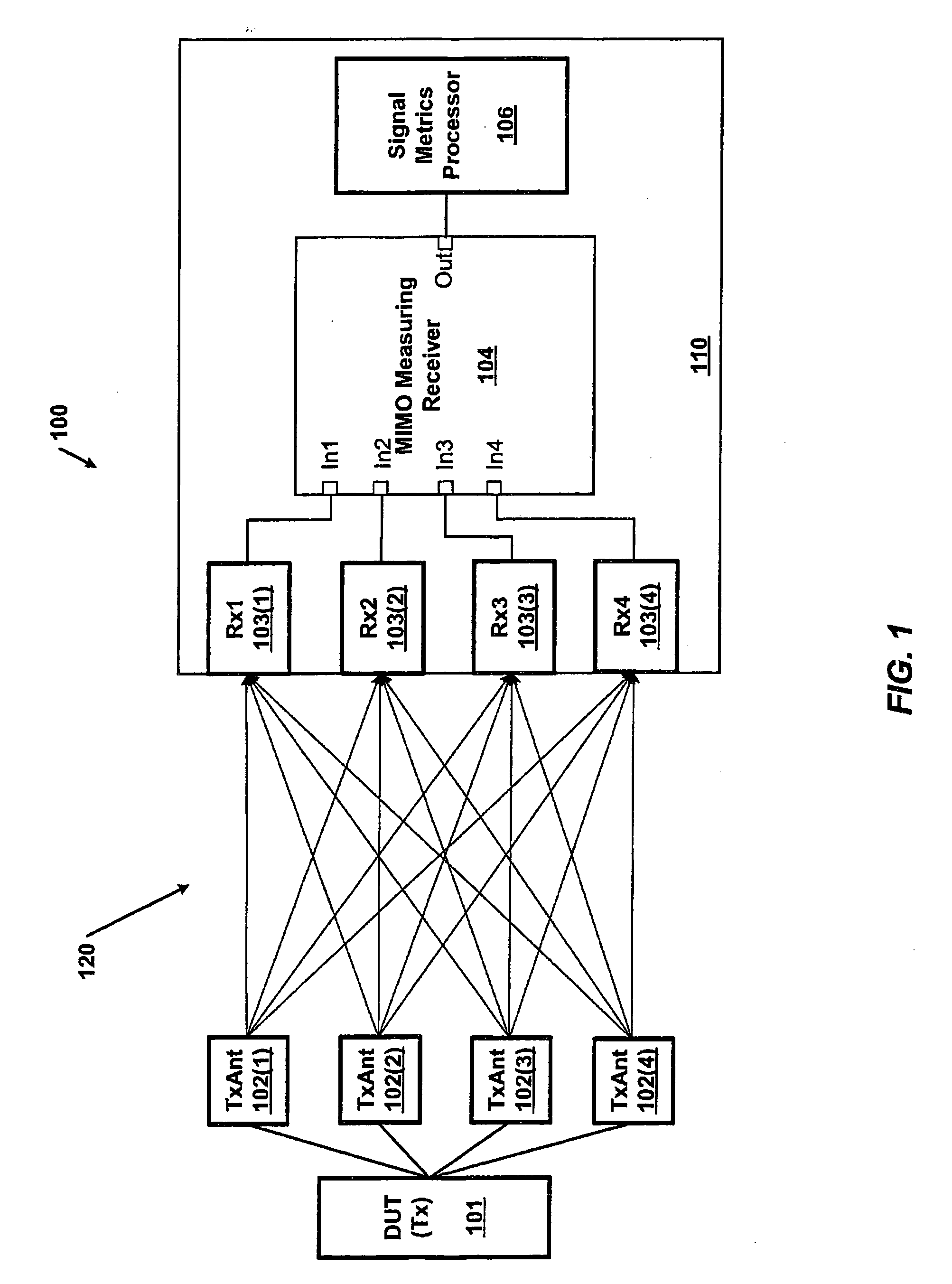
[0029]FIG. 1 is a diagram of an example of a system 100 for analyzing a MIMO system using a MIMO measurement receiver 104. The system 100 in FIG. 1 includes a MIMO transmitter 101 connected to four transmitter antennas 102(1)-(4). The MIMO transmitter 101 sends via its antennae 102(1)-(4) multiple transmissions through a propagation medium to a MIMO receiver 110 with the ability to receive multiple input signals simultaneously. For example, FIG. 1 shows the transmitter 101 sending signals via the four transmitting antennae 102(1)-(4) over a set of MIMO channels 120. The channels 120 are receiv...


PUM


Abstract

Systems and methods for receiving MIMO signals for testing and analyzing operation of MIMO communications devices. Examples of systems and/or methods for receiving MIMO signals include a measuring receiver with N RF paths consisting of N downconverters. Each downconverter achieves a frequency shift of the input MIMO signal equal to a shifting frequency of a first intermediate frequency (IF) plus a delta determined by the signal bandwidth multiplied by an integer number between 1 and N. The shifted N MIMO signals are combined to generate one combined analog MIMO signal. An analog to digital converter converts the combined analog MIMO signal to a stream of digital samples where the samples may be tested and analyzed with metrics on signals communicated in a MIMO environment. Example systems and method for receiving MIMO signals may also be implemented as a MIMO channel emulator such that samples generated by the ADC may be upconverted to output copies of the original signals to a receiver DUT, for example.

Description

BACKGROUND OF THE INVENTION[0001]Commercial communication systems are being developed to exploit the use of multiple transmitters and receivers to take advantage of characteristics of the communication medium. A communication medium, such as over-the-air signals from antenna, creates alternative signal propagation paths with different impairment characteristics. In the presence of high impairments in a challenging transmission environment, traditional use of multiple transmitters and receivers reaches a limit in data throughput capacity. MIMO (Multiple Input Multiple Output) communication systems increase data capacity over traditional systems by combining information about the diversity created by impairments in the signal propagation paths with the use of multiple transmitters and receivers. One example of a MIMO system is a mobile telecommunications system where mobile handsets communicate data to other mobile handsets over a MIMO communication interface. An example of such a mob...

Claims


Application Information

Patent Timeline
Patent Type & Authority Applications(United States)
IPC IPC(8): H04B7/10
CPCH04B7/04H04L1/06H04B17/0087
Inventor CHEN, HELENAVENELL, BRIAN J.STRACHAN, GORDON R.LAWTON, MICHAEL C.
Owner AGILENT TECH INC
Why Eureka
Try Eureka