Vehicle equipped with motor and inverter

a technology of inverter and motor, which is applied in the direction of electric generator control, dynamo-electric converter control, dynamo-electric gear control, etc., can solve the problems of increasing the conduction loss of inverter, increasing the heat generation amount, and not being able to sufficiently increase the carrier frequency fc relative to output frequency fv, etc., to reduce noise, reduce cost, and improve fuel consumption

Active Publication Date: 2010-03-04
DENSO CORP
View PDF4 Cites 78 Cited by
  • Summary
  • Abstract
  • Description
  • Claims
  • Application Information

AI Technical Summary

Benefits of technology

[0014]An object of this invention is to provide a vehicle of achieving reduction of noise, reduction of cost and improvement of fuel consumption in a balanced manner.

Problems solved by technology

Therefore, it is not possible to sufficiently increase carrier frequency fc relative to output frequency fv in order to suppress the switching loss.
Particularly when high torque is generated, an inverter conduction loss is increased and a heat generation amount is also increased.
However, when the inverter is designed so as to drive with high carrier frequency in all operating regions, size of the inverter becomes bigger and the cost of the inverter is increased.
When carrier frequency fc is simply decreased in order to reduce the switching loss, a controllability of the motor is deteriorated.
Therefore, since there is a risk of vibration of the vehicle due to pulsation of the torque and breakage of parts due to out-of-control on an electric current, it is not allowable to simply decrease carrier frequency fc.
However, conversely at the time of low torque such as steady traveling with little noise inside the vehicle, there is a possibility that an electromagnetic sound by inverter switching is annoying.
Although frequency of the sound can be changed by changing the pulse number, it is not possible to arbitrarily change the frequency due to restriction of synchronization.
Therefore, the switching loss is increased, a problem of overheat in the inverter is caused, and hence there is a cost problem in order to prepare an inverter resistant to the above problem.
Therefore, in a case where carrier frequency fc is set to be higher than necessary, there is a possibility of an increase in the loss and a deterioration of the fuel consumption.
In other words, since too much importance is conventionally given to improvement of the controllability and the reduction of the noise, there is sometimes a case where the cost of the inverter is high and there is some room for improving the fuel consumption.

Method used


Image

  • Vehicle equipped with motor and inverter
  • Vehicle equipped with motor and inverter
  • Vehicle equipped with motor and inverter

Examples


first embodiment

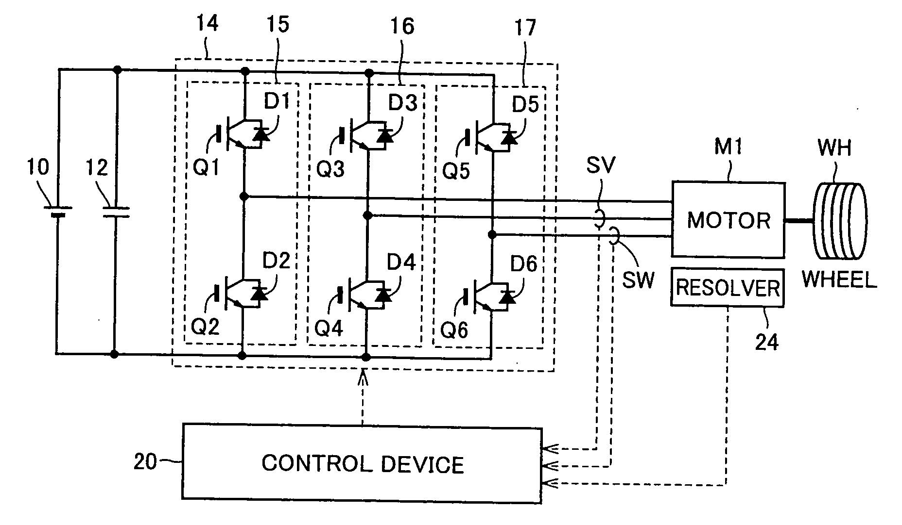
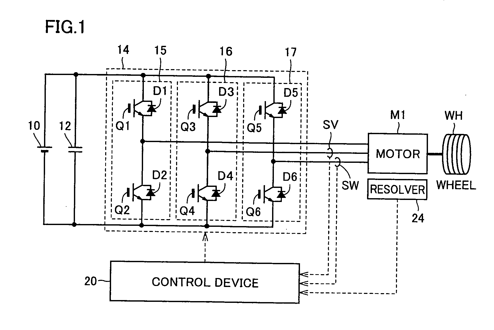
[0035]FIG. 1 is a circuit diagram showing a configuration of a motor drive device used in the present invention.

[0036]With reference to FIG. 1, this motor drive device includes a DC power supply 10, a capacitor 12, an inverter 14, current sensors SV and SW, a motor M1, a resolver 24, and a control device 20.

[0037]The DC power supply may be made of a secondary battery such as a nickel hydride battery, a lithium ion battery and a lead battery and the like. A large-capacity capacitor or a fuel cell may also be used together with or instead of the secondary battery.

[0038]Inverter 14 receives power supply voltage from DC power supply 10 and drives AC motor M1. Preferably, inverter 14 performs a regenerative operation at the time of braking motor M1 and returns electric power generated in AC motor M1 to DC power supply 10.

[0039]Inverter 14 includes a U phase arm 15, a V phase arm 16 and a W phase arm 17. U phase arm 15, V phase arm 16 and W phase arm 17 are connected in parallel between o...

second embodiment

[0080]In the first embodiment, the control is performed by focusing on a point of switching between the synchronization of the carrier frequency with the voltage command value and the non-synchronization thereof In a second embodiment, the control is performed by focusing on a loss of the inverter and a total loss of the motor and the inverter.

[0081]That is, in the second embodiment, the carrier frequency is determined so that the inverter loss is minimized in the region of a large electric current with high heat generation of the inverter, and the carrier frequency is determined so that the total loss of the motor and the inverter is minimized in other regions.

[0082]FIG. 9 is a diagram showing changes of the inverter loss and the total loss in a case where the carrier frequency is changed.

[0083]In FIG. 9, the carrier frequency is indicated by a lateral axis and the losses are indicated by a vertical axis. When the carrier frequency is increased, the inverter loss is increased in ac...

third embodiment

[0101]A third embodiment is to combine the first and second embodiments.

[0102]FIG. 12 is a diagram for illustrating carrier switching control executed in the third embodiment.

[0103]With reference to FIG. 12, a region A7 is a region where the IGBT device is driven with the minimum-required pulse number in the synchronous PWM control so as to protect the inverter from the overheat. A region A8 is a region where the IGBT device is driven with using the carrier frequency to minimize the total loss of the motor and the inverter so as to improve the fuel consumption with the best efficiency. A region A9 is a region where the torque is small, that is, acceleration and deceleration are not executed very often, and also a region where the carrier frequency to minimize the noise inside the vehicle is selected.

[0104]FIG. 13 is a flowchart for illustrating control executed in the third embodiment. Processing of this flowchart is invoked from the main routine of the traveling control of the vehi...


PUM


Abstract

A vehicle includes a motor for driving wheels WH, an inverter to drive the motor, and a control device to perform PWM control of the inverter. The control device performs synchronous PWM control in a case where an electric current supplied to the motor by the inverter or torque generated in the motor is larger than a threshold value; and performs the synchronous PWM control or non-synchronous PWM control in a case where the electric current or the torque is smaller than the threshold value and sets carrier frequency or a pulse number of the PWM control to be higher than the case where the electric current or the torque is larger than the threshold value. Thereby, it is possible to provide a vehicle of achieving reduction of noise, reduction of cost and improvement of fuel consumption in a balanced manner.

Description

[0001]This nonprovisional application is based on Japanese Patent Application No. 2008-218166 filed on Aug. 27, 2008 with the Japan Patent Office, the entire contents of which are hereby incorporated by reference.BACKGROUND OF THE INVENTION[0002]1. Field of the Invention[0003]This invention relates to a vehicle, particularly to a vehicle equipped with an inverter to drive a motor for driving the vehicle and a control device thereof.[0004]2. Description of the Background Art[0005]In recent years, an eco-friendly vehicle to use a motor for driving the vehicle such as an electric vehicle, a hybrid vehicle and a fuel cell vehicle is drawing public attention.[0006]Japanese Patent Laying-Open No. 09-070195 discloses a control device of a motor capable of handling even in a case where rapid heat generation is caused in a switching device. In a case where a rotation speed of the motor is sufficiently low, this motor control device determines that the motor is locked by external force and sw...

Claims


Application Information

Patent Timeline
Patent Type & Authority Applications(United States)
IPC IPC(8): H02P6/08B60L9/18H02M7/48H02P21/05H02P21/22H02P23/04H02P27/08
CPCB60L11/18B60L11/1803B60L15/2045Y02T10/7283H02P27/08Y02T10/644Y02T10/7005B60L2220/14B60L50/51B60L50/75Y02T10/64Y02T10/70Y02T10/72Y02T90/40
Inventor TAKAMATSU, NAOYOSHIOKAMURA, MASAKI
Owner DENSO CORP
Why Eureka
Try Eureka