Lighting arrangement

a lighting arrangement and light technology, applied in the field of lighting arrangement, can solve the problems of high cost and bulky components, low power loss of diodes, and low lighting arrangemen

Active Publication Date: 2006-04-18
SIGNIFY NORTH AMERICA CORP
View PDF8 Cites 74 Cited by
  • Summary
  • Abstract
  • Description
  • Claims
  • Application Information

AI Technical Summary

Benefits of technology

[0007]Since it is possible to control the difference between the DC input voltage Vin and the DC output voltage Vout at a comparatively low value, it is possible to operate a LED array in a lighting arrangement according to the invention without making use of a transformer. As a result, the lighting arrangement is comparatively cheap and small.
[0010]Preferably, a capacitor is coupled between the output terminals. Such a capacitor stabilizes the voltage between the output terminals and thereby also the voltage over the LED array.

Problems solved by technology

A disadvantage of such a transformer is that it is an expensive and bulky component.
As a result, the lighting arrangement is comparatively cheap and small.
As a result power losses in the diode are comparatively low.

Method used


Image

  • Lighting arrangement
  • Lighting arrangement

Examples


Embodiment Construction

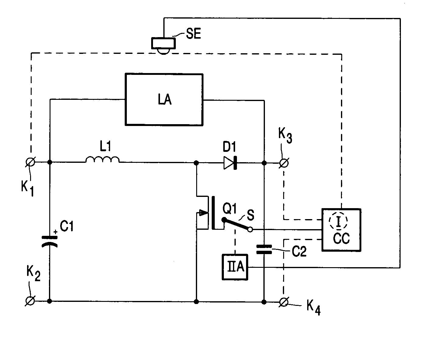
[0016]In FIG. 1, K1 and K2 are first and second input terminals respectively for connection to a supply voltage source supplying a DC input voltage Vin. Input terminal K1 and input terminal K2 are connected by means of a capacitor C1 and by means of a series arrangement of an inductive element L1 and a switching element Q1. A control electrode of switching element Q1 is connected to an output of circuit part CC via a switching element S. Circuit part CC is a control circuit for generating a control signal for rendering the switching element Q1 periodically alternately conductive and non-conductive. Circuit part CC comprises means I, coupled to the input terminals and the output terminals (indicated by means of dotted lines), for controlling a time lapse Ton, during which the switching element is maintained in a conductive state during each period of the control signal, proportional to Vout / Vin2. Switching element Q1 is shunted by a series arrangement of diode D1 and capacitor C2. A ...


PUM


Abstract

In a lighting arrangement comprising a LED array and a DC-DC-converter for supplying the LED array, the DC-DC-converter is an up-converter and the LED array is coupled between an input terminal and an output terminal. The up-converter generates a very low voltage over the LED array without making use of a transformer.

Description

BACKGROUND[0001]1. Field of Invention[0002]The invention relates to a lighting arrangement comprising a LED array and a circuit arrangement for supplying the LED array.[0003]2. Description of Related Art[0004]A lighting arrangement as mentioned in the opening paragraph is known from WO 01 / 05193. The known lighting arrangement is used for instance as a backlight in a Liquid Crystal Display. The DC-DC-converter that is used is of the flyback type. Since the voltage that is present over the LED array is comparatively low, the DC-DC-converter generally needs to comprise a transformer. A disadvantage of such a transformer is that it is an expensive and bulky component.[0005]It is an object of the invention to provide a lighting arrangement in which the disadvantage described above is absent.SUMMARY[0006]According to embodiments of the present invention, a lighting arrangement includes an LED array coupled between an input terminal and an output terminal.[0007]Since it is possible to cont...

Claims


Application Information

Patent Timeline
Patent Type & Authority Patents(United States)
IPC IPC(8): H05B37/00F21V8/00F21Y101/02H02M3/155H05B37/02H05B44/00
CPCH05B33/0815H05B33/0851Y02B20/346Y02B20/30H05B45/12H05B45/38
Inventor NIJHOF, ENGBERT BERNARD GERARDBUCKS, MARCEL JOHANNES MARIACLAESSENS, JOHANNES MATHEUS THEODORUS LAMBERTUSDE KRIJGER, JOZEF PETRUS EMANUEL
Owner SIGNIFY NORTH AMERICA CORP
Why Eureka
Try Eureka