Packet switch control with layered software

a software control and data switch technology, applied in data switching networks, time-division multiplexing selection, wireless communication, etc., can solve problems such as network geographical limitations, system reboot in order to implement fault correction, and other obstacles, and achieve efficient distribution of software control functions.

Inactive Publication Date: 2002-06-04
NORTHROP GRUMMAN SYST CORP
View PDF6 Cites 82 Cited by
  • Summary
  • Abstract
  • Description
  • Claims
  • Application Information

AI Technical Summary

Benefits of technology

Throughput efficiency is achieved through optimization of the distribution of layered software control functions and application software to each one of multiple general processors (GPs) and digital signal processors (DSPs). In particular, there is layering of: (a) firmware optimized for specific hardware control or I / O data movement functions; (b) a real-time operating system for general purpose processing; (c) software executives optimized for DSP and embedded I / O control functions; and (d) application software distributed and optimized to each DSP and GP. This feature allows the combination of GPs and DSPs for efficient distribution of software control functions. In the event of a failure of any one processor, tasks can be redistributed or a switch can be made to a different processor.

Problems solved by technology

The necessity of rebooting the system in order to implement fault correction is a major disadvantage in a communications satellite responsible for providing switching for a large amount of data packets.
Packet switch 100 is thus generally unacceptable for installation in extremely remote locations and the network thus has geographical limitations, such as those imposed by large bodies of water and by space.
Remote locations also present other obstacles.
For example, during a long period of operation in orbit, several processors and other elements of a communications satellite may fail.

Method used


Image

  • Packet switch control with layered software
  • Packet switch control with layered software
  • Packet switch control with layered software

Examples


Embodiment Construction

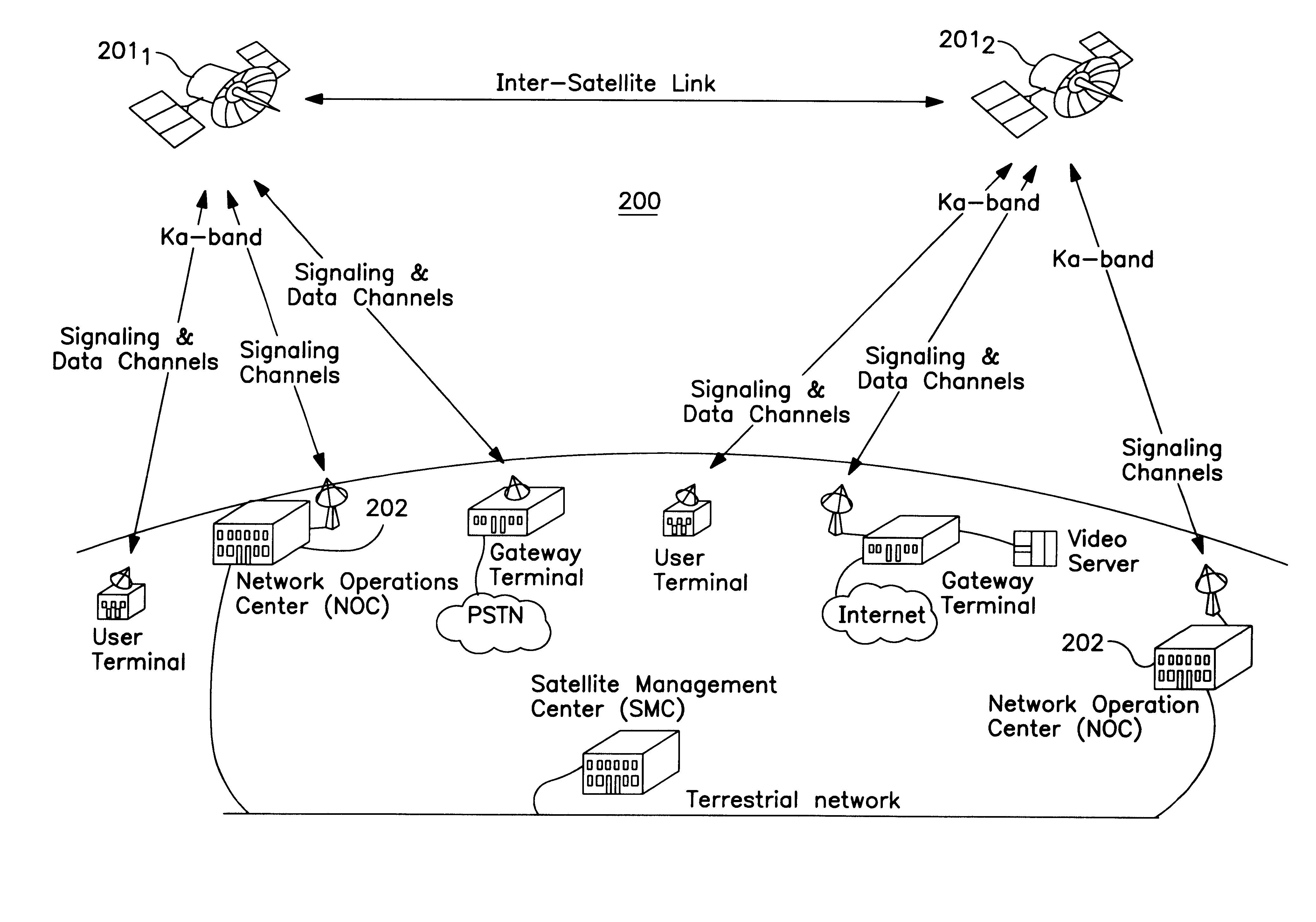
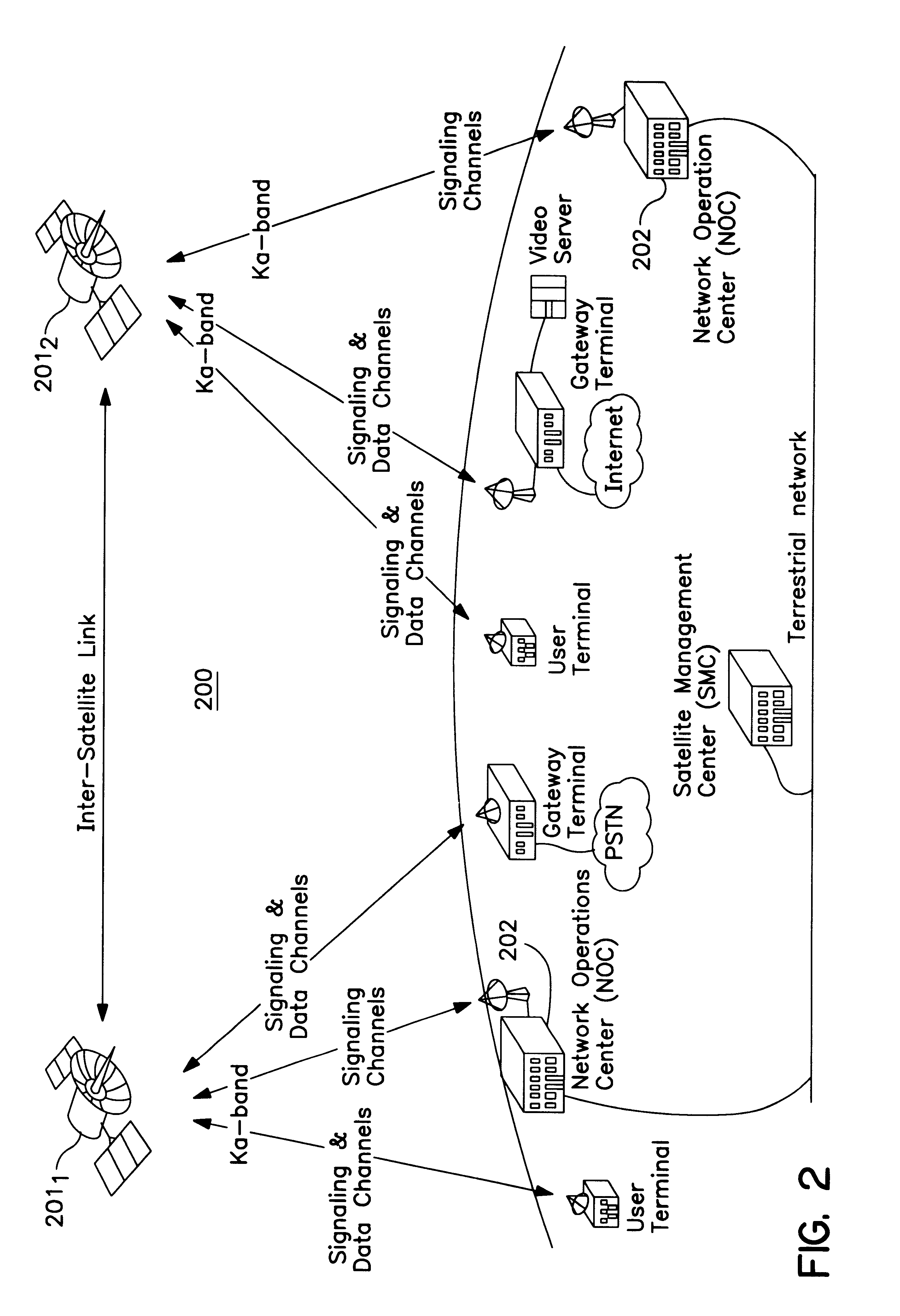
It is an object of the following preferred embodiments of the invention to provide a global packet data communications system. In particular, the preferred embodiments preferably include packet switches installed on board satellites located in a geosynchronous, medium earth, or low earth orbit in space. The satellites of these embodiments are preferably capable of operating in different communications applications.

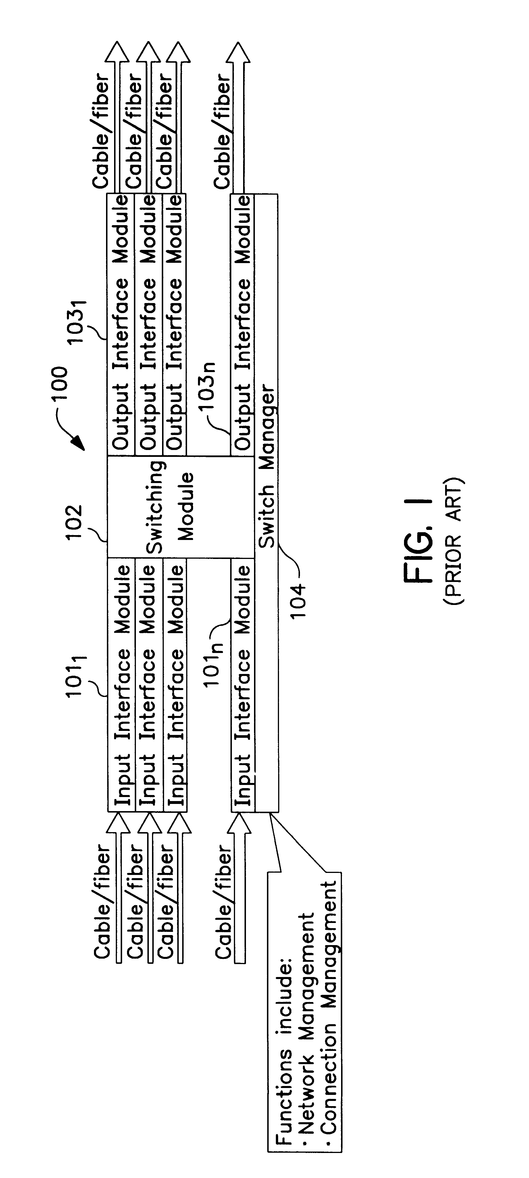
As part of the preferred embodiments, it is a particular object to provide a fast cell / packet switch having a general software architecture particularly well suited for the above objects. The software architecture of the fast cell / packet switch is preferably flexible so as to be able to satisfy the communications desires of different users. In particular, the switch must be able to operate at speeds higher than conventional packet switches and must be able to implement fault correction without the need for rebooting.

A real-time control processor is used in the communicatio...


PUM


Abstract

A communications satellite (201) has an on-board high speed packet switch for switching transmitted data packets. The packet switch (502) is part of a processor subsystem (501) which also includes a number of demodulators (5031 to 503n) demodulating signals received from an uplink downconverter. All of the processors in the processor subsystem (501) are organized into a loosely coupled, distributed, architecture of general purpose computer modules (601) and digital signal processor modules (602) having both primary and redundant processors and being connected to each other by dual redundant PCI buses. Software and firmware is layered and distributed redundantly over the processor modules (601, 602).

Description

1. Field of the InventionThis invention relates generally to data communications systems and methods. In particular, the present invention relates to a packet data switch controller suitable for implementation in a communications satellite.2. Description of Related ArtSwitched packet data communications systems and methods are well known in the art. Perhaps the most prevalent examples of switched packet data communications systems are those utilizing the Asynchronous Transfer Mode (ATM) network protocol developed to efficiently move information at a faster rate. The networks of switched packet data communications systems include a number of packet switches of otherwise minimum functionality which move user information encapsulated into packets (sometimes referred to as cells) from an input port to an output port. In addition to the user (or payload) data, these packets have a header containing information to be used inside the network for routing, error correction, flow control, etc...

Claims


Application Information

Patent Timeline
Patent Type & Authority Patents(United States)
IPC IPC(8): H04B7/185H04L12/56H04Q11/04H04B7/15
CPCH04B7/18515H04B7/18589H04L49/203H04L49/254H04Q11/0478H04L49/3081H04L49/552H04L49/255H04L2012/5608H04L2012/5627
Inventor TIRABASSI, MARIA A.ARENBERG, EDWARD A.
Owner NORTHROP GRUMMAN SYST CORP
Why Eureka
Try Eureka