
Simultaneous multiple channel receiver

a receiver and simultaneous technology, applied in the field of digital communication, can solve the problems of dbs system drawback, known satellite equipment used for receiving satellite video transmissions is not as user-friendly, and known satellite equipment typically lacks the ability to allow a user to utilize two or more reception channels simultaneously

Active Publication Date: 2005-09-01
NXP BV
View PDF5 Cites 79 Cited by
  • Summary
  • Abstract
  • Description
  • Claims
  • Application Information

AI Technical Summary

Benefits of technology

The patent describes a device called a simultaneous multiple channel receiver (SMCR) that can receive a combined signal with multiple carrier signals. The SMCR breaks down the combined signal and produces multiple output data stream signals simultaneously. This allows for the simultaneous transmission of data on multiple channels. The device includes a down-converter front-end, digital signal processors, and a multi-band filter. The technical effect of this invention is the ability to receive and process multiple carrier signals simultaneously, resulting in faster data transmission and improved efficiency.

Problems solved by technology

Unfortunately, known satellite equipment utilized for receiving satellite video transmissions are not as user friendly as the old terrestrial analog television equipment.
Specifically, known satellite equipment typically lacks the ability to allow a user to utilize two or more reception channels simultaneously.
In a typical home environment this is a drawback for DBS systems compared to, as an example, standard non-DBS analog cable systems (i.e., cable television) and old terrestrial analog television equipment (i.e., standard over-the-air television and radio transmissions generally known as “terrestrial transmission systems”).
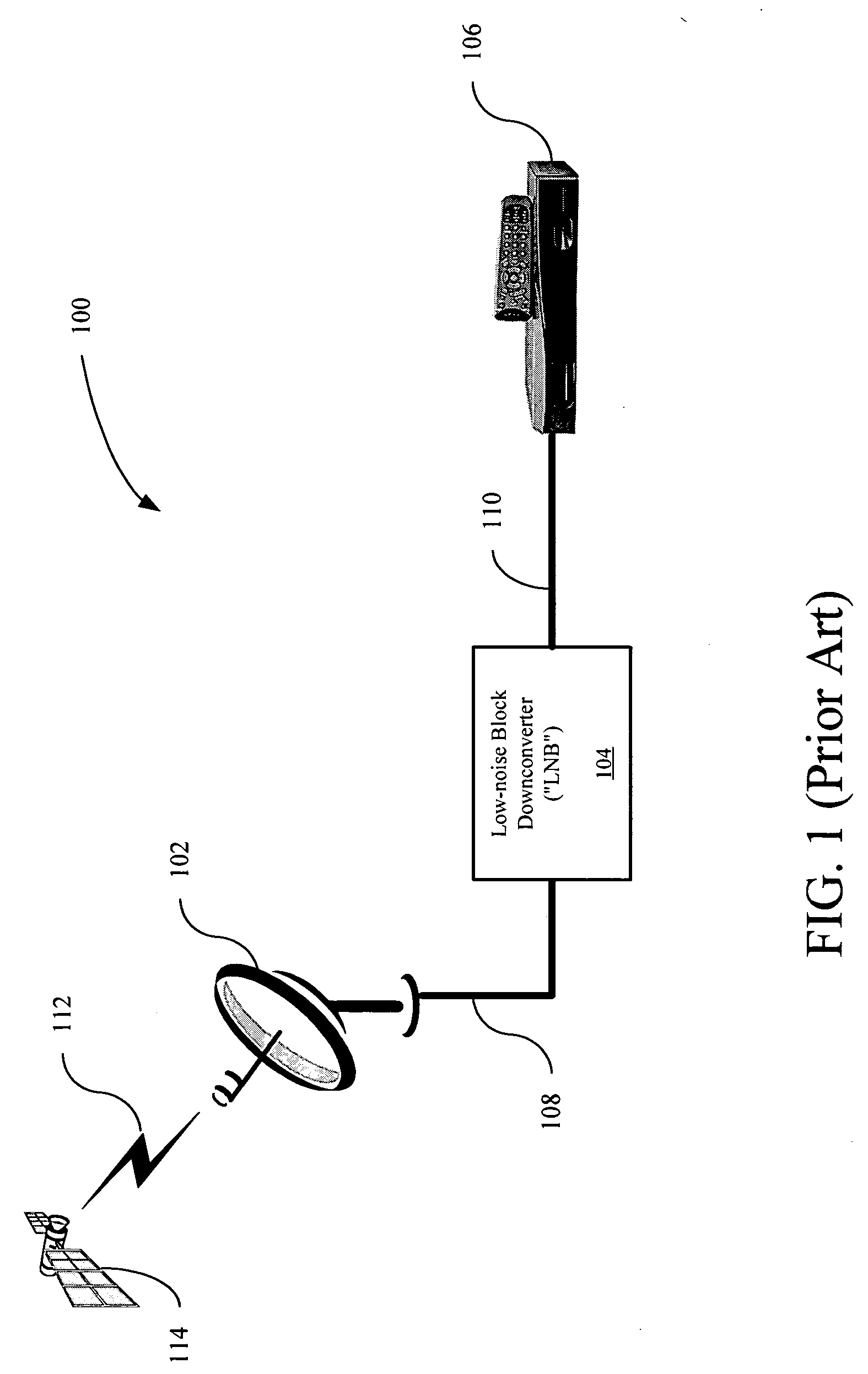
Unfortunately, the DBS satellite reception system 100 is not capable of allowing multiple STBs to connect to the LNB 104 and provide independent simultaneous channel reception by each individual STB.
However, these solutions are multi-cable approaches that are high cost and cumbersome to arrange in the typical home environment because they entail the increased cost of equipment such as multiple cables, multi-switch devices, combiners and splitters and the cost of labor in professionally installing the equipment.
Once the equipment has been installed it is pseudo-permanent in nature because it is difficult to rearrange the equipment in the future.
These approaches are still much more complicated than adding additional cable-ready tuners in a home-installed cable television system.
Therefore, allowing an end-user to view one frequency channel on a video monitor while simultaneously recording another frequency channel on a video recorder and / or watching one of more frequency channels within the typical picture-in-picture functions of most modern video monitors is not possible because generally known state-of-the-art DBS satellite STBs (such as STB 106) typically utilize, as an example, a STB architecture 300 shown in FIG. 3, where the STB architecture 300 is only capable of demodulating and decoding one frequency channel at a time.
Unfortunately, the STB architecture 300 is unable to demodulate multiple DBS satellite frequency channels simultaneously because it describes a single tuner-demodulator architecture.
Unfortunately, the multiple channel tuner-demodulator 400 is too complex and expensive for consumer applications.

Method used


Image

  • Simultaneous multiple channel receiver
  • Simultaneous multiple channel receiver
  • Simultaneous multiple channel receiver

Examples


Embodiment Construction

[0040] In the following description of the preferred embodiments, reference is made to the accompanying drawings that form a part hereof, and in which is shown by way of illustration specific embodiments in which the invention may be practiced. It is to be understood that other embodiments may be utilized and structural changes may be made without departing from the scope of this invention.

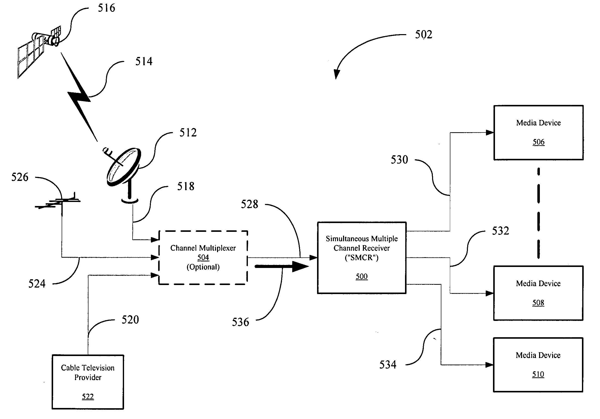
[0041] In FIG. 5, a Simultaneous Multiple Channel Receiver (“SMCR”) 500 is shown within a multi-channel reception system (“MRS”) 502. The MRS 502 may be a DBS satellite ground system and / or multi-channel cable television reception system capable of receiving and demodulating received cable television signals carrying multiple cable television channels as described by the next-generation cable project known as Next Generation Network Architecture (“NGNA”).

[0042] In an example of the MRS 502 including a DBS satellite ground system, the MRS 502 may include the SMCR 500, an optional channel multiple...


PUM


Abstract

A simultaneous multiple channel receiver (“SMCR”) for receiving a combined signal having a plurality of carrier signals, where each carrier signal in the plurality of carriers signals corresponds to a frequency channel, and in response, simultaneously producing a plurality of output data stream signals, is disclosed. The SMCR may include a down-converter front-end capable of receiving the combined signal, a plurality of digital signal processors, wherein each digital signal processor of the plurality of digital signal processors is capable of producing an output data stream signal of the plurality of output data stream signals, and a multi-band filter in signal communication with both the down-converter front-end and the plurality of digital signal processors.

Description

CROSS-RELATED APPLICATIONS[0001] This application claims priority under 35 U.S.C. 119(e) to U.S. Provisional Application Ser. No. 60 / 484,183, titled “Simultaneous Multiple Channel Demodulator,” filed Jun. 30, 2003, and U.S. Provisional Application Ser. No. 60 / 534,176, titled “Satellite Multi-Choice Switch System,” filed Dec. 31, 2003, both of which applications are incorporated in their entirety into this application by reference.BACKGROUND OF THE INVENTION [0002] 1. Field of the Invention [0003] The invention generally relates to the area of digital communication. Specifically the invention relates to a system capable of receiving satellite transmissions. [0004] 2. Related Art [0005] The utilization of digital communication systems is growing at a rapid pace in modern society. Specifically, digital communication systems have become more common because they typically provide a higher level of performance than analog communication systems. As a result, communication systems such as t...

Claims


Application Information

Patent Timeline
Patent Type & Authority Applications(United States)
IPC IPC(8): H04H1/00H04H20/28H04H40/18H04H40/90H04L12/28H04N5/44
CPCH04H20/28H04H40/18H04H40/90H04N5/4401H04N21/4385H04N21/42607H04N21/43615H04N21/4382H04N21/44209H04N21/426
Inventor HESS, KENDAL MCNAUGHT-DAVISGILL, MANJIT S.EIDSON, DONALD BRIANNEE, CHI-PINGLINDSTROM, MATSKRIEGER, ABRAHAMHARRIS, FRED
Owner NXP BV
Learn More