Radio communication apparatus, transmitter apparatus and receiver apparatus

Inactive Publication Date: 2010-04-13
NAT INST OF INFORMATION & COMM TECH +1
View PDF14 Cites 95 Cited by
  • Summary
  • Abstract
  • Description
  • Claims
  • Application Information

AI Technical Summary

Benefits of technology

[0033]Further, the radio communication device, transmitter and receiver multiplex the frequency band of the user range on the intermediate frequency band of satellite broadcast and the frequency band of ground wave broadcast. Consequently, a frequency modul

Problems solved by technology

Therefore, in a house, video signals from a plurality of electronic devices and broadcast wave signals cannot be radio-connected.
Further, a plurality of such electronic devices cannot be carried to different rooms and used simultaneously at the different places.
In the configuration of using three kinds of transmission units, when stability of the frequency of the frequency modulator fluctuates, stable demodulation cannot be performed on the reception side.
Consequently, an oscillator of high stability cannot b

Method used


Image

  • Radio communication apparatus, transmitter apparatus and receiver apparatus
  • Radio communication apparatus, transmitter apparatus and receiver apparatus
  • Radio communication apparatus, transmitter apparatus and receiver apparatus

Examples


first embodiment

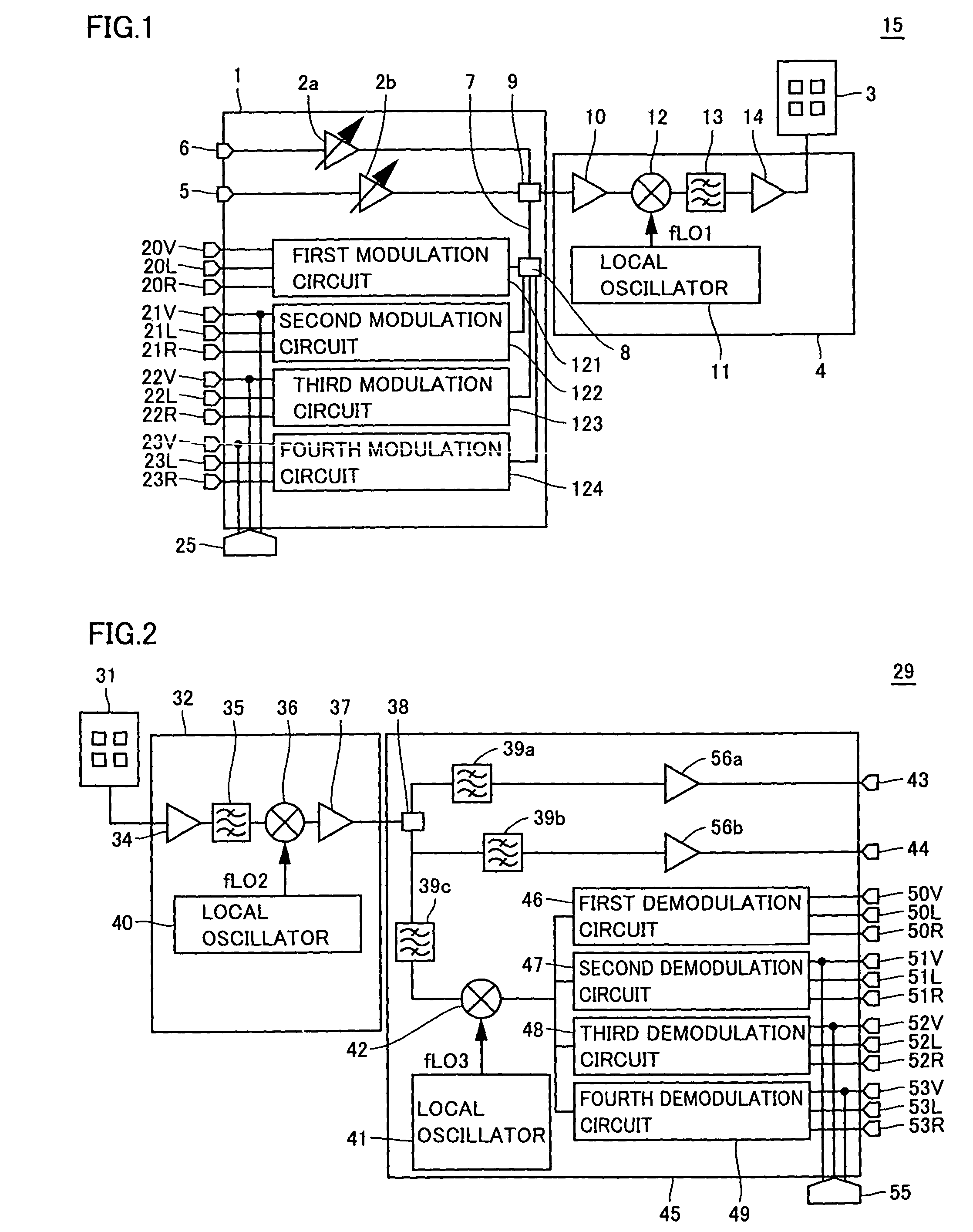
[0047]A radio communication device according to a first embodiment will be described. The radio communication device according to the first embodiment includes a millimeter-wave transmitter 15 shown in FIG. 1 and a millimeter-wave receiver 29 shown in FIG. 2.

[0048]Millimeter-wave transmitter 15 will be described. Millimeter-wave transmitter 15 has an IF multiplexing circuit 1, a millimeter-wave up-converter 4, and a millimeter antenna 3.

[0049]IF multiplexing circuit 1 will be described. First and second TV (television) broadcast waves are inputted to connection terminals 6 and 5, respectively. Each of the first and second TV broadcast waves includes intermediate frequency waves of a satellite broadcast. The first and second TV broadcast waves are subjected to level adjustment by amplifiers 2a and 2b respectively and, after that, the resultant signals are combined with an output of a signal synthesizer 8 which will be described later by a signal coupler 9. By signal coupler 9, a freq...

second embodiment

[0102]A radio communication device according to a second embodiment will be described. The radio communication device according to the second embodiment has millimeter-wave transmitter 15 and millimeter-wave receiver 29 described as basic configuration.

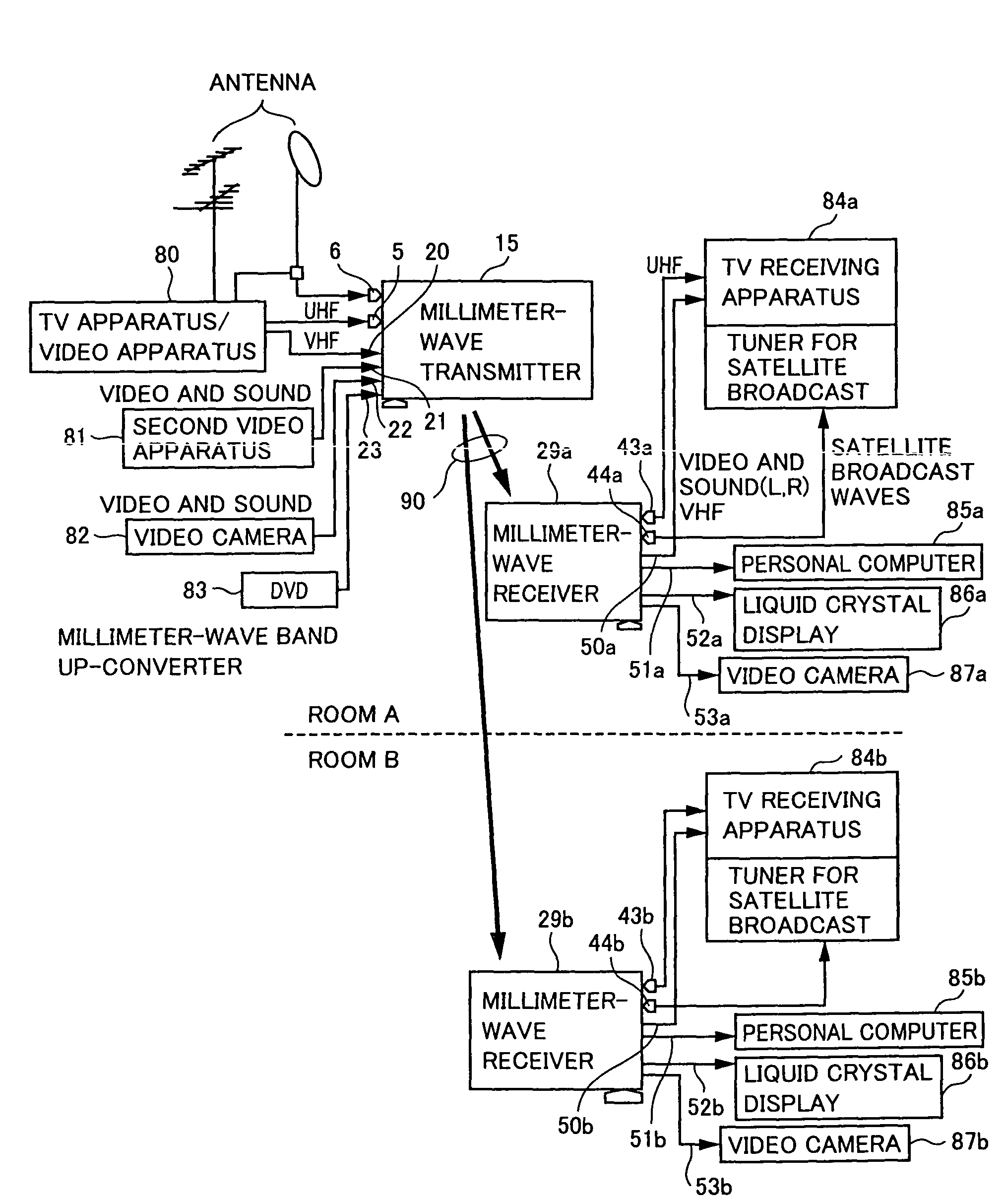
[0103]A use example of the radio communication device according to the second embodiment will be described by referring to FIG. 6. FIG. 6 shows an example of disposing one millimeter-wave transmitter 15 and one millimeter-wave receiver 29a in room A of a house and one millimeter-wave receiver 29b is disposed in room B which is different from room A. In the second embodiment, in place of second video apparatus 81, video camera 82 and DVD 83, a digital video recorder 91 for outputting a video component signal is used.

[0104]In the second embodiment, the video component signal is transmitted by using three terminals 21, 22 and 23 out of four terminals receiving the user range signal waves. The video component signal is constructed by lumi...


PUM


Abstract

The present invention provides a radio communication device, a transmitter and a receiver capable of handling a plurality of signal waves. A radio communication device has a millimeter-wave transmitter (15) and a millimeter-wave receiver (29). Millimeter-wave transmitter (15) includes a multiplexing circuit (1), a millimeter-wave up-converter (4) and an antenna (3), and the millimeter-receiver includes an antenna (31), a millimeter-wave down-converter (32) and an output processing circuit (45). The signal waves dedicated to the user are modulated by a modulation circuit (121 to 124) so as to be allocated between the ground broadcast waves and satellite broadcast waves. The frequencies are multiplexed in an intermediate frequency band, after that, the multiplexed frequencies are converted into a millimeter-wave band and the resultant is transmitted. On the reception side, the multiplexed waves are down-converted, separated to signal waves and demodulated.

Description

[0001]This application is the national phase under 35 U.S.C. §371 of PCT International Application No. PCT / JP01 / 09105 which has an International filing date of Oct. 17, 2001, which designated the United States of America.TECHNICAL FIELD[0002]The present invention relates to a radio communication device, a transmitter and a receiver, and more particularly to a radio communication device, a transmitter and a receiver for radio-transmitting a plurality of kinds of signals.BACKGROUND ART[0003]As an example of a millimeter-wave band transmitter / receiver for transmitting and receiving signals in a millimeter-wave band, there is a video transmission system of a 50 GHz band described in “New Version of 50 GHz Simple Radio Equipment” (The 1997 IEICE General Conference C-2-123, pp. 178) (Literature 1).[0004]The millimeter-wave band transmitter / receiver in Literature 1 includes a transmitter 1100 shown in FIG. 10A and a receiver 1150 shown in FIG. 10B. As will be described below, each of trans...

Claims


Application Information

Patent Timeline
IPC IPC(8): H04J3/04H04N5/38H04B1/26H04B1/40H04B7/15H04B7/185H04H20/00H04H20/02H04H20/74H04N5/44H04N7/08H04N7/081
CPCH04B1/005H04B1/406H04H20/74H04B7/18506H04H20/02H04B7/15
Inventor SUEMATSU, EIJIOGAWA, HIROYOHAMAGUCHI, KIYOSHISHOJI, YOZO
Owner NAT INST OF INFORMATION & COMM TECH
Why Eureka
Try Eureka