Curved hammer

a hammer and hammer mill technology, applied in the field of comminuting or grinding materials, can solve the problems of requiring immediate maintenance and repair, severe damage to the hammermill, and wear of the hammer over a relatively short period of operation,

Active Publication Date: 2013-12-24
GENESIS III
View PDF9 Cites 11 Cited by
  • Summary
  • Abstract
  • Description
  • Claims
  • Application Information

AI Technical Summary

Problems solved by technology

One significant problem with hammer mills is the wear of the hammers over a relatively short period of operation in reducing “dirty” products which include materials such as nails, dirt, sand, metal, and the like.
As found in the prior art, even though a hammermill is designed to better handle the entry of a “dirty” object, the possibility exists for catastrophic failure of a hammer causing severe damage to the hammermill and requiring immediate maintenance and repairs.
However, because the weight of the hammer increased, the capacity of the unit typically will be decreased because of horsepower limitations.

Method used


Image

  • Curved hammer
  • Curved hammer
  • Curved hammer

Examples


first embodiment

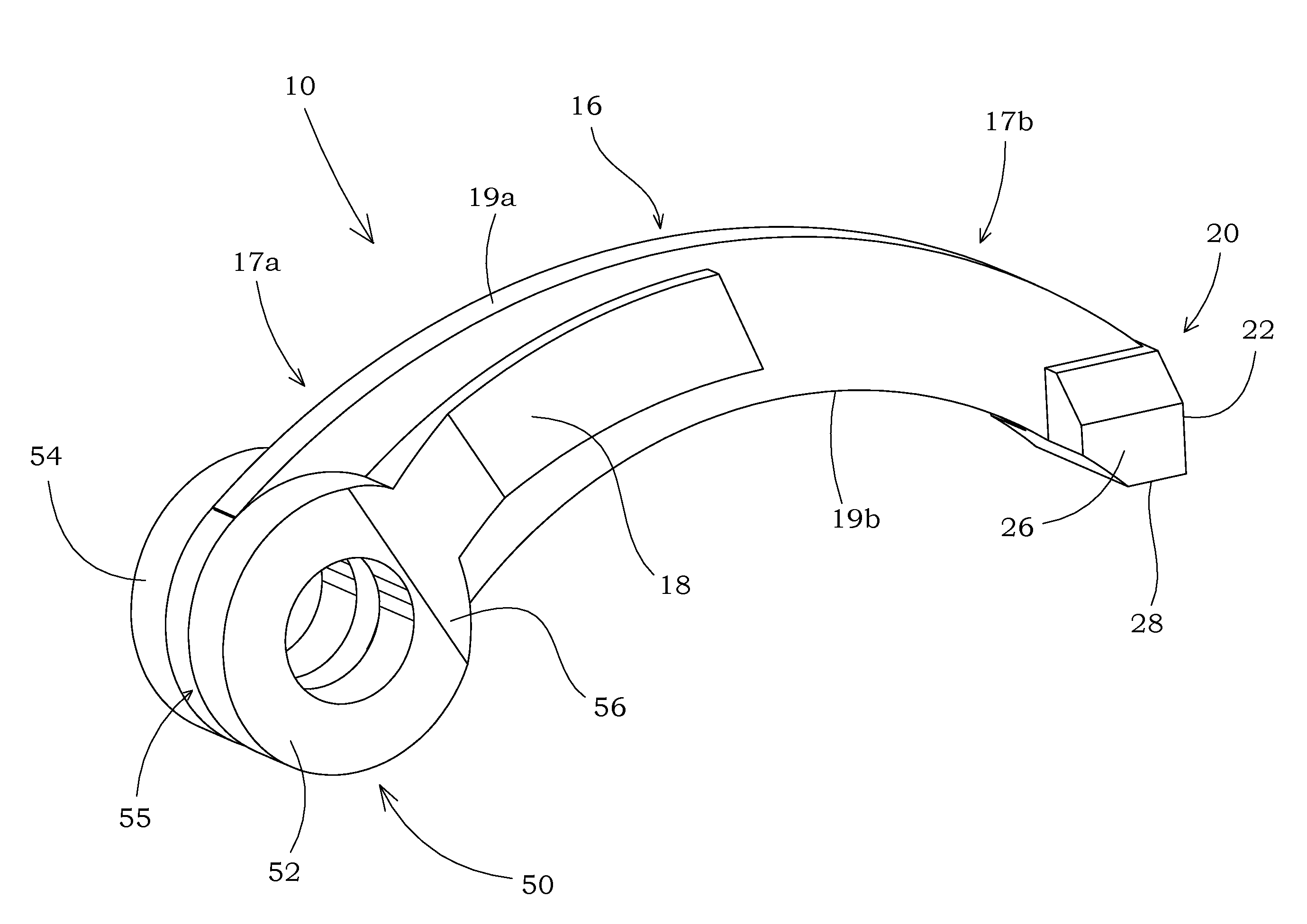
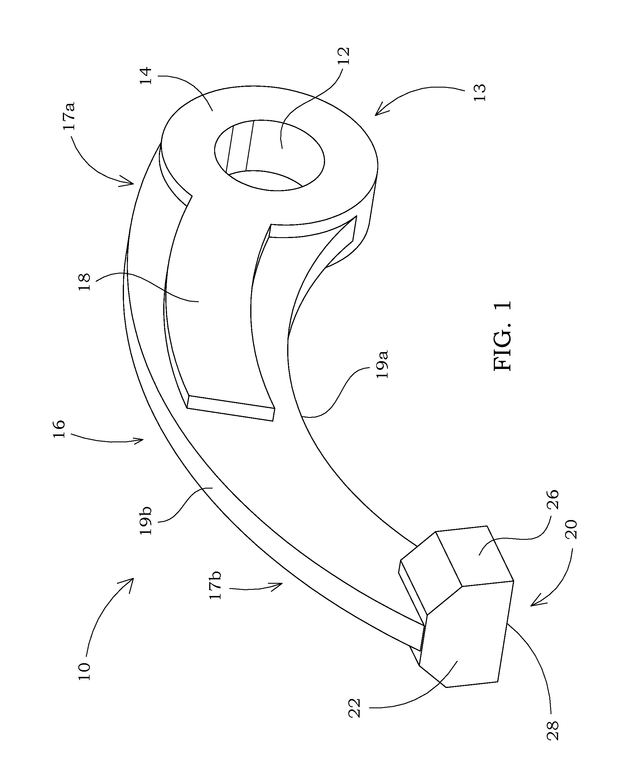
[0025]A shoulder 14 may be positioned on the connection portion 13 surrounding the rod hole 12, as shown in the various embodiments pictured herein. The shoulder 14 provides increased strength and longevity to the curved hammer 10 in many applications, as is well known to those skilled in the art. In the various embodiments pictured herein, the shoulder 14 is positioned on both sides of the rod hole 12. However, in other embodiments not pictured herein, the shoulder 14 is positioned on only one side of the rod hole 12. The optimal dimensions of the shoulder 14 will vary depending on the specific application of the curved hammer 10, and are therefore in no way limiting to the scope of the curved hammer 10. In the first embodiment, the thickness of the shoulder 14 is 0.75 inches.

[0026]As best shown in FIG. 1, the neck 16 of the curved hammer 10 is non-linear. As shown in the first embodiment herein, the neck bottom surface 19a is derived from a circle having a radius of four and one-h...

second embodiment

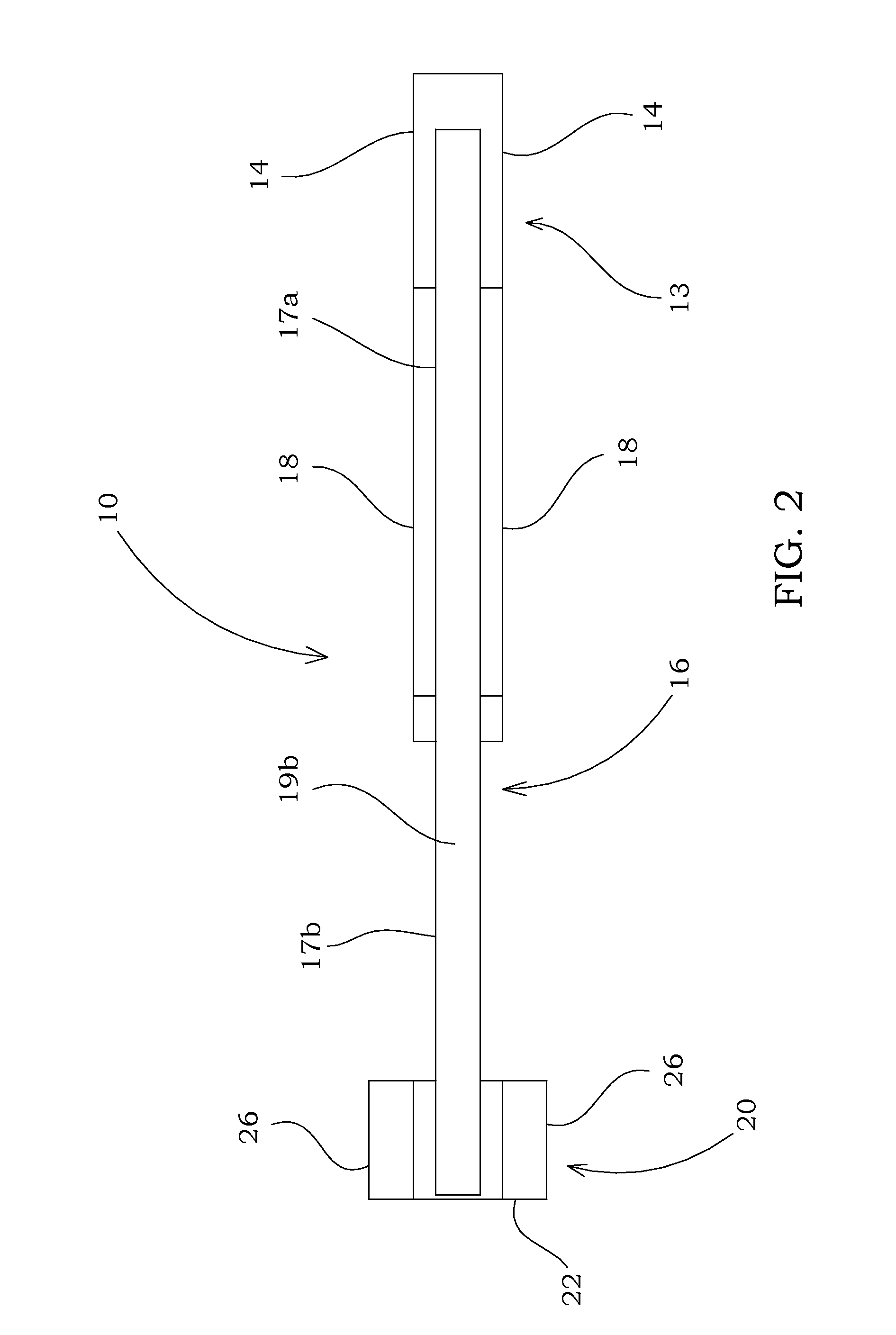
[0031]In the second embodiment, the curvature of the neck bottom surface 19a continues through the contact portion 20 and terminates at the bottom contact surface 28. The surface of the contact portion 20 through which the neck bottom surface 19a extends may have the same curvature as that of the neck bottom surface 19a, as shown in FIG. 4. However, in other embodiments, different orientations, angles, or dimensions of the contact portion 20, primary contact surface 22, side contact surface 26, and bottom contact surface 28, may be present without departing from the spirit and scope of the curved hammer 10.

[0032]In the second embodiment of the curved hammer 10, a plurality of welds 24 is affixed to the primary contact surface 22. These welds 24 may be of a hardened material to increase the efficacy and longevity of the curved hammer 10. The materials used to create a weld 24 will vary depending on the specific application of the curved hammer 10, which includes consideration for the...

third embodiment

[0036]The precise distance the void 55 extends through the rod hole 12 may be different in different embodiments not pictured herein, and is therefore in no way limiting to the scope of the curved hammer 10. Furthermore, the precise width of the void 55 (i.e., the distance between the interior surfaces of the first and second arms 52, 54) may be different from one embodiment to the next. In embodiments of the curved hammer 10 not pictured herein, the first and second arms 52, 54 may extend past the rod hole 12 in the direction opposite the neck second end 17b by an amount greater than that shown for the third embodiment pictured herein.

[0037]The curved hammer 10 may be installed in a hammermill assembly to rotate in any direction. However, it is contemplated that from the vantage shown in FIGS. 2A and 4, the curved hammer 10 will rotate in a counterclockwise direction. Accordingly, with most embodiments of a hammermill assembly in the prior art, the curved hammer 10 allows the prima...


PUM


Abstract

The various embodiments disclosed and pictured illustrate a curved hammer for comminuting various materials. The illustrative embodiments pictured and described herein are primarily for use with a rotatable hammermill assembly. The curved hammer includes a connection portion having a rod hole therein, a contact portion for delivery of energy to the material to be comminuted, and a curved neck portion affixing the connection portion to the contact portion. In other embodiments, a shoulder is positioned around the periphery of the rod hole for added strength. In still other embodiments, a neck reinforcement is positioned along a portion of the neck for increased strength. A weld or plurality of welds may be affixed to various surfaces of the contact portion to aide in comminuting and / or longevity of the curved hammer.

Description

CROSS REFERENCE TO RELATED APPLICATIONS[0001]The present non-provisional patent application is a continuation of and claims priority from U.S. patent application Ser. No. 12 / 786,202 filed on May 24, 2010, now U.S. Pat. No. 8,141,804 issued Mar. 27, 2012 which application claimed priority from provisional U.S. Pat. App. No. 61 / 180,773, filed on May 22, 2009, both of which are incorporated by reference herein in their entireties.FIELD OF INVENTION[0002]This invention relates generally to a device for comminuting or grinding material. More specifically, the invention is especially useful for use as a hammer in a rotatable hammermill assembly.STATEMENT REGARDING FEDERALLY SPONSORED RESEARCH OR DEVELOPMENT[0003]No federal funds were used to develop or create the invention disclosed and described in the patent application.REFERENCE TO SEQUENCE LISTING, A TABLE, OR A COMPUTER PROGRAM LISTING COMPACT DISK APPENDIX[0004]Not ApplicableBACKGROUND[0005]A number of different industries rely on i...

Claims


Application Information

Patent Timeline
Patent Type & Authority Patents(United States)
IPC IPC(8): B02C13/28
CPCB02C13/28
Inventor YOUNG, ROGER T.
Owner GENESIS III
Why Eureka
Try Eureka