Steering wheel vibration damping system

a technology of vibration damping and steering wheel, which is applied in the direction of pedestrian/occupant safety arrangement, vehicular safety arrangement, vehicle components, etc., can solve the problems of braking mechanism, vibration of steering wheel, and “bump-squeak-rattle effect”

Inactive Publication Date: 2013-12-31
AUTOLIV ASP INC
View PDF11 Cites 20 Cited by
  • Summary
  • Abstract
  • Description
  • Claims
  • Application Information

AI Technical Summary

Problems solved by technology

While driving, the steering wheel can often experience vibrations which are passed on to the operator.
The vibrations can be the result of imbalance in the tires or wheels, wheels mounted off-center, roughness or unevenness of the road or other driving surface, roughness of the braking mechanism, etc.
The vibrations can also lea

Method used


Image

  • Steering wheel vibration damping system
  • Steering wheel vibration damping system
  • Steering wheel vibration damping system

Examples


Embodiment Construction

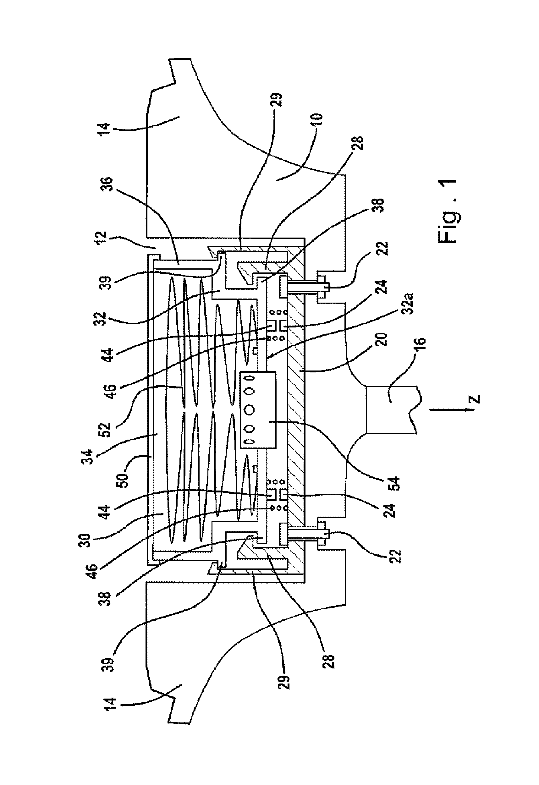
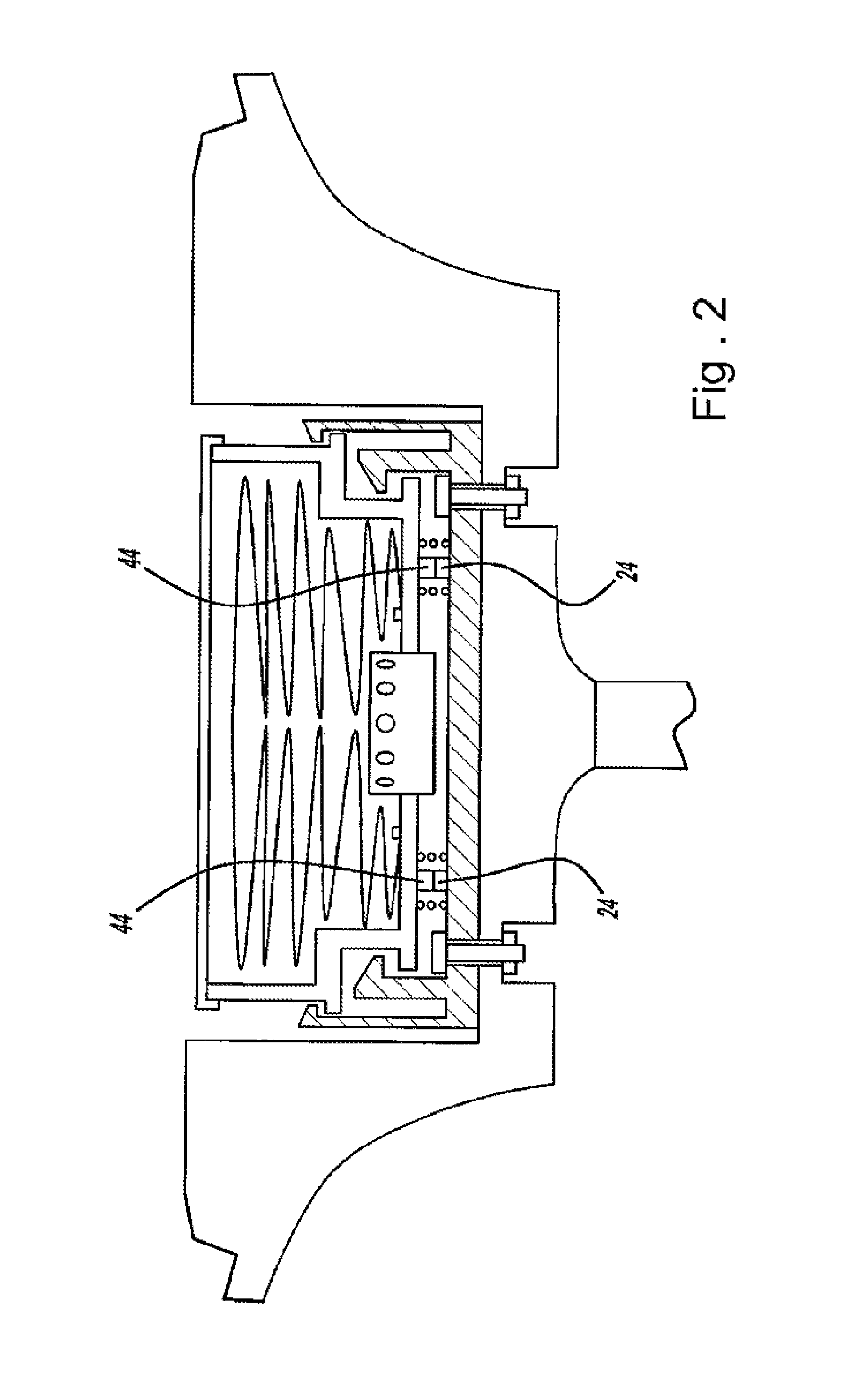
[0051]Referring now to the figures, the invention will now be explained in more detail with reference to exemplary embodiments. The basic mounting arrangement, which will now be explained in more detail with reference to FIGS. 1 to 3, generally applies to each embodiment.

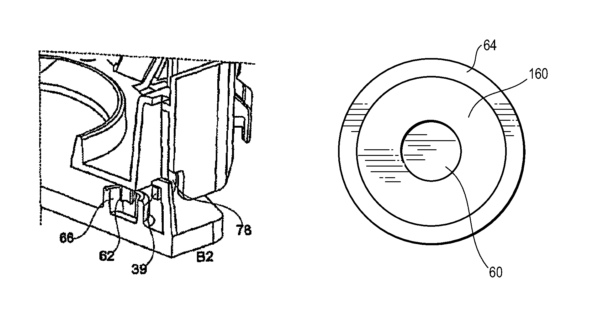
[0052]FIG. 1 shows a longitudinal section through the hub area of a steering wheel unit in schematic form. This steering wheel unit includes a steering wheel with a steering wheel body 10, which has a recess 12 in the hub area. Spokes 14 extend from the hub area. Steering column 16 extends from the approximate center of the hub. The direction of extension of steering column 16 defines the axial or Z direction for what is to follow. The plane which is perpendicular to this Z direction (this plane is also perpendicular to the drawing plane of FIG. 1) is the XY plane.

[0053]On the floor of recess 12, a mounting plate 20 is screwed together with steering wheel body 10 by means of screws 22, in other words is connected to...


PUM


Abstract

A steering wheel unit includes a steering wheel body and an airbag module mounted thereto. The airbag module includes positioning means for maintaining the axial positioning of the airbag module relative to the steering wheel and positioning means for maintaining the radial positioning of the airbag module relative to the steering wheel. The steering wheel unit also includes damping elements that are disposed between the insertion elements and receiving elements of the radial positioning means. The radial positioning means can be in the form of a post within a cylindrical receptacle, where the damping element is therebetween. The radial positioning means can be in the form of a plate received within a u-shaped receiving element, where the damping element is within the u-shaped receiving element.

Description

BACKGROUND[0001]1. Field of the Invention[0002]The present invention generally relates to a steering wheel unit for a motor vehicle having an airbag module incorporated into the steering wheel.[0003]2. Description of the Related Art[0004]Motor vehicle steering wheels allow the vehicle operator to control the steering of the vehicle, as is well known in the art. While driving, the steering wheel can often experience vibrations which are passed on to the operator. The vibrations can be the result of imbalance in the tires or wheels, wheels mounted off-center, roughness or unevenness of the road or other driving surface, roughness of the braking mechanism, etc. The vibrations can also lead to a “bump-squeak-rattle” effect due to the various components mounted to the steering wheel. Vibrations and “bump-squeak-rattle” in the steering wheel can affect the comfort of the operator while driving.[0005]One type of component mounted to the steering wheel is a vehicle airbag module. The airbag...

Claims


Application Information

Patent Timeline
IPC IPC(8): B60R21/203
CPCB60R21/2037
Inventor MATSU, RICHARD LAWRENCEPALM, DAVID R.SODERSTROM, JAN PONTUS
Owner AUTOLIV ASP INC
Why Eureka
Try Eureka