AI technical title is built by Patsnap AI team. It summarizes the technical point description of the patent document.
a radar detector and wireless connectivity technology, applied in the field of radar detectors, can solve the problems of radar detectors not being able to tell the difference between the emissions of many of these devices and the emissions of true police radar systems, radar detectors increasingly generating false alarms, and undermining the credibility of radar detector performan
Active Publication Date: 2014-01-07
ESCORT INC
View PDF89 Cites 16 Cited by
Summary
Abstract
Description
Claims
Application Information
AI Technical Summary
This helps you quickly interpret patents by identifying the three key elements:
Problems solved by technology
Method used
Benefits of technology
Problems solved by technology
The growing number of such signals is rapidly undermining the credibility of radar detector performance.
Radar detectors cannot tell the difference between emissions from many of these devices and true police radar systems.
As a result, radar detectors are increasingly generating false alarms, effectively “crying wolf”, reducing the significance of warnings from radar detectors.
However certain locations near airports have been demonstrated to cause such problems for various laser detector products.
For example, a common problem with navigation devices with GPS capability is that data on the device may not updated.
Method used
Image
Click on the blue label to locate the original text in one second.
Reading with bidirectional positioning of images and text.
Examples
Embodiment Construction
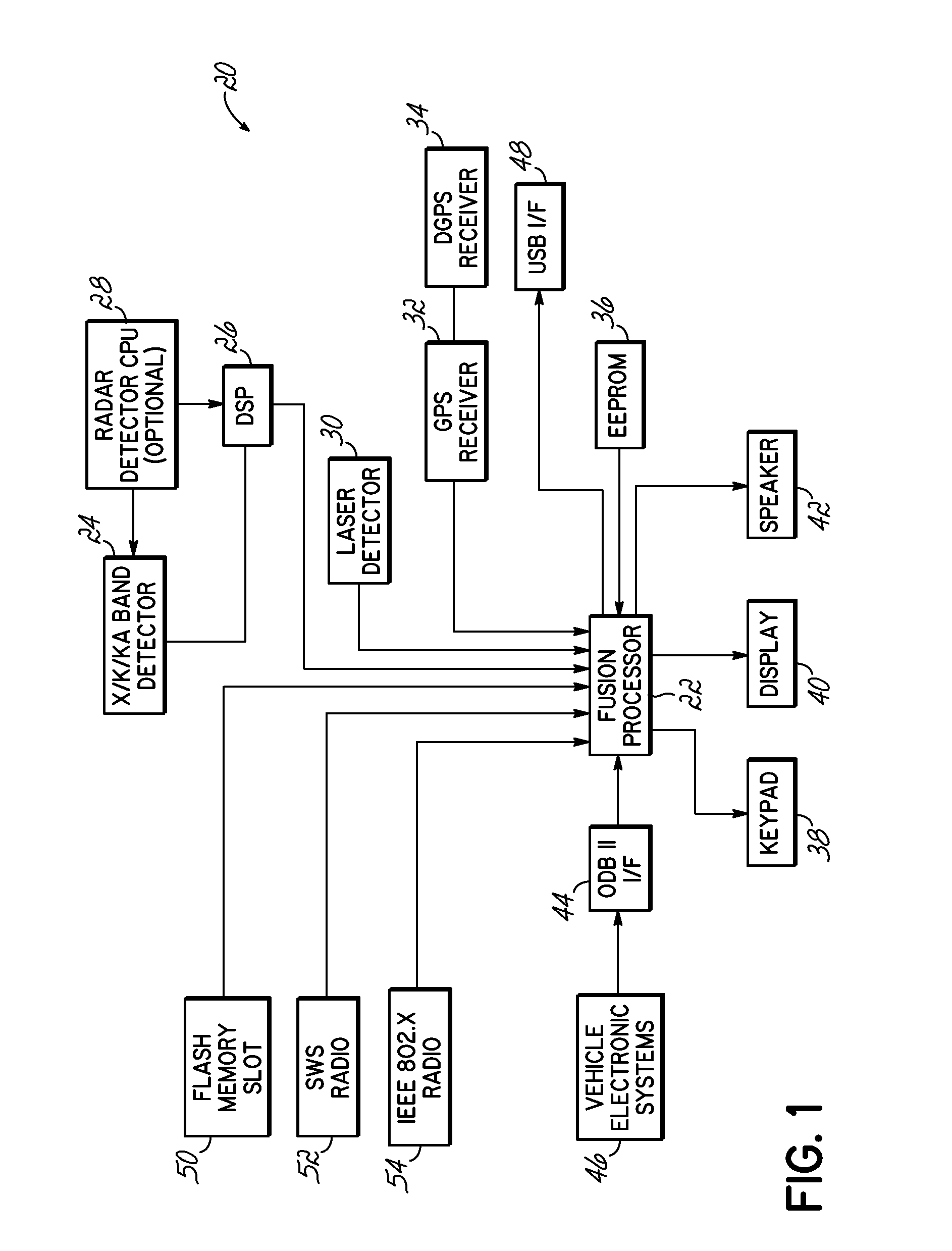
[0049]Referring now to FIG. 1, the radar detector 20 in accordance with principles of the present invention includes a processor 22 for controlling all functions of the unit. Processor 22 receives information on radar signals from a conventional X / K / KA band microwave receiver 24, coupled to processor 22 via a digital signal processor (DSP) 26. Microwave receiver 24 and DSP 26 may utilize any of the techniques described above and in the above-referenced patents, for rejecting noise and increasing discrimination between actual and spurious police radar signals. Further, receiver 24 and DSP 26 may be controlled by an optional second CPU 25, which can enable additional signal evaluation beyond that which is possible using a DSP.
[0050]Processor 22 is further connected to a laser detector 30 for detecting police LIDAR signals. Processor 22 is further connected to a GPS receiver 32 and a separate differential GPS (DGPS) receiver 34, such that differential GPS methodologies may be used wher...
PUM
Abstract
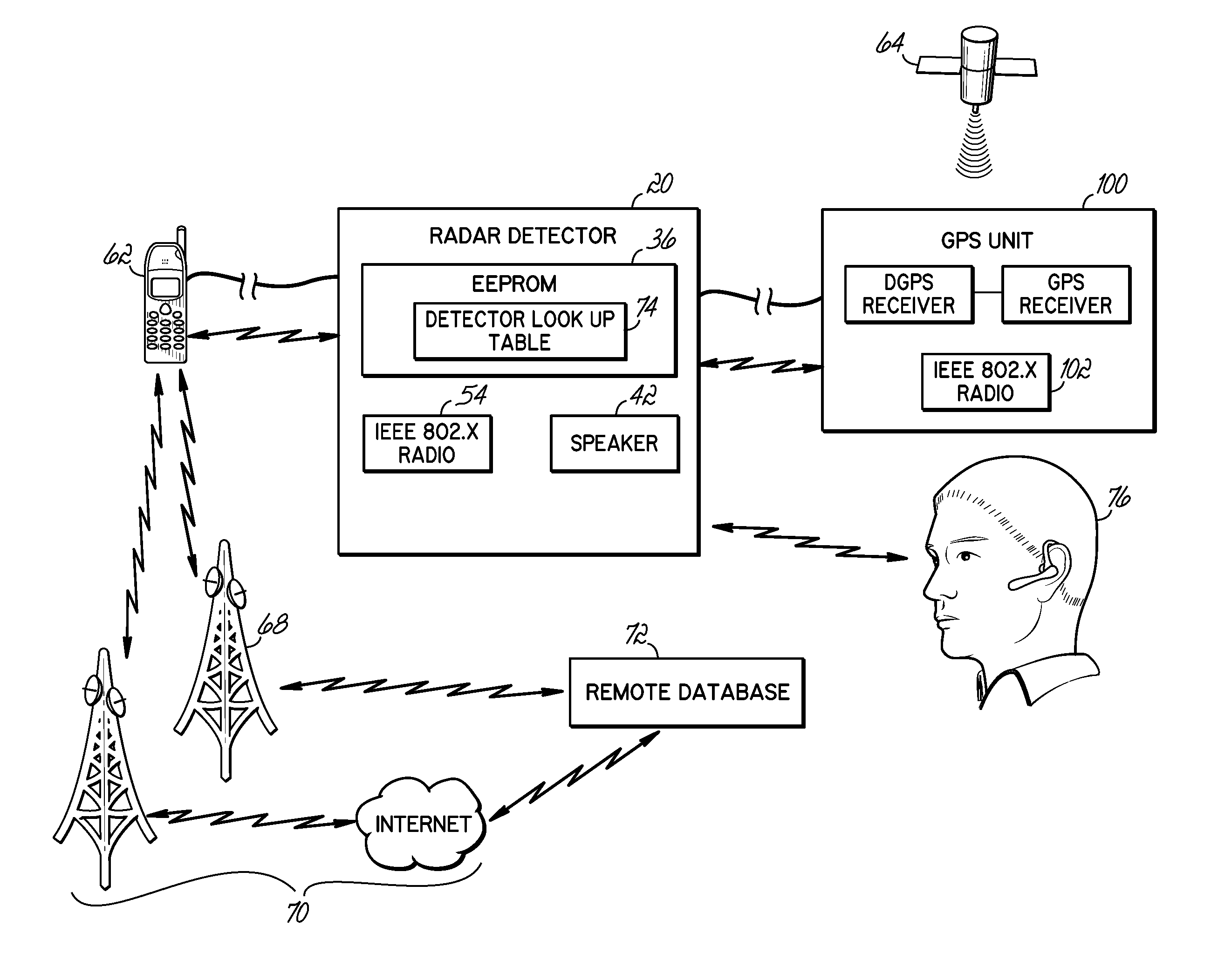
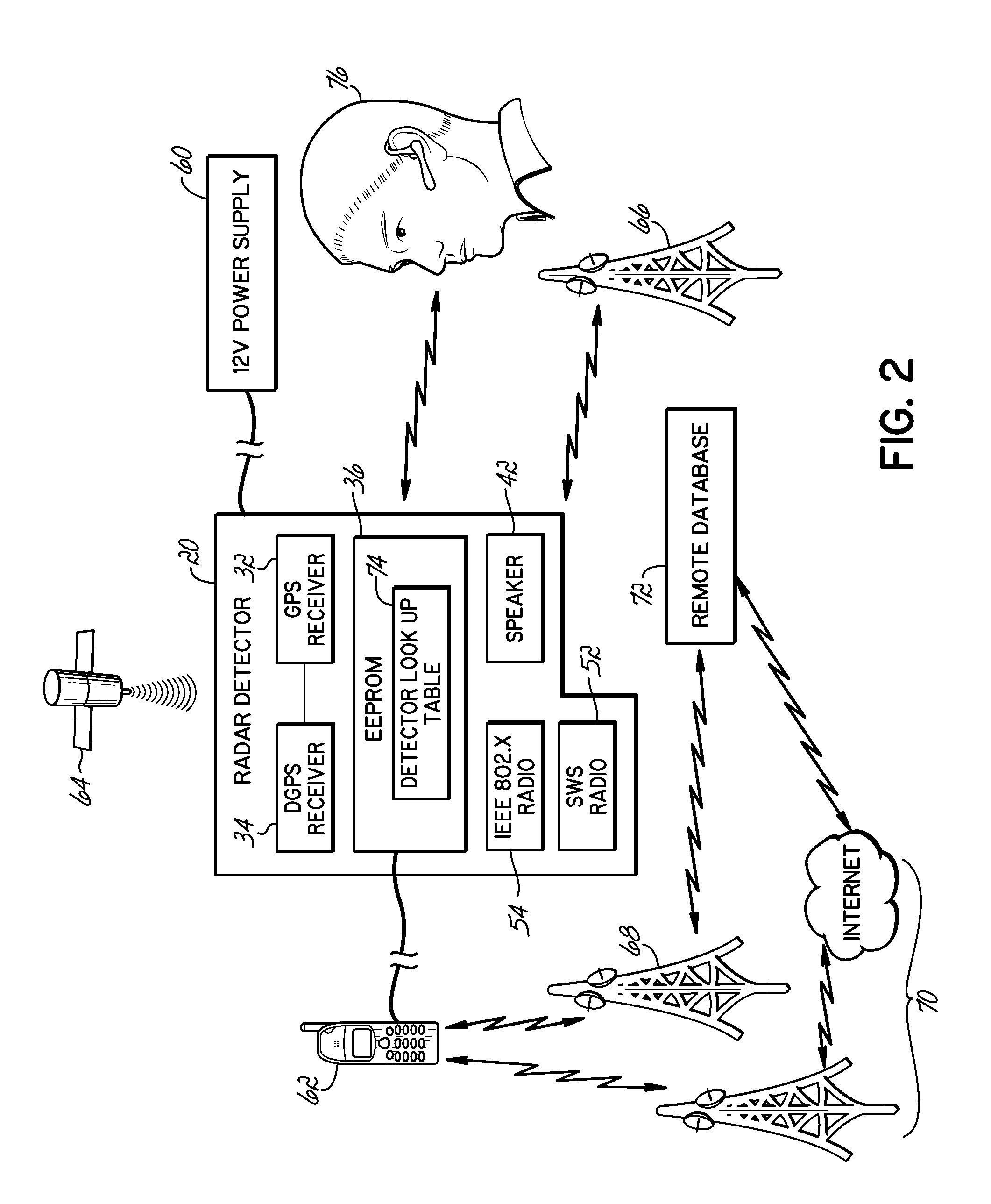
Wireless and other external connectivity technology is used in various ways to enhance or improve upon existing radar detector and police activity detection systems. External memory interfaces, such as SD cards or USB, provide external storage. Wireless interfaces such as Bluetooth, Zigbee, 802.11, and wireless personal area network communication protocols, allow a detector processor to interact wirelessly with external devices, such as a Bluetooth headset, a cellular network device providing a server connection, or toggle buttons used to indicate the presence of police activity at a current position. Further, radar detectors are upgraded to provide GPS capabilities, using the existing power / data connector of the radar detector.
Description
CROSS-REFERENCE TO RELATED APPLICATIONS[0001]This application is a continuation-in-part application of U.S. Ser. No. 12 / 389,978 filed Feb. 20, 2009, and claims the benefit of Ser. No. 12 / 389,978 filed on Feb. 20, 2009. This application is also related to U.S. Ser. No. 11 / 620,443 filed Jan. 5, 2007, U.S. Ser. No. 10 / 396,881, filed Mar. 25, 2004, and U.S. Pat. No. 6,670,905, each of which claim benefit of U.S. Provisional Patent Application Ser. No. 60 / 139,097, filed Jun. 14, 1999, and U.S. Provisional Patent Application Ser. No. 60 / 145,394, filed Jul. 23, 1999. All of these applications are hereby incorporated herein in their entirety.FIELD OF THE INVENTION[0002]The present invention relates to radar detectors.BACKGROUND OF THE INVENTION[0003]Radar detectors warn drivers of the use of police radar, and the potential for traffic law citations if the driver exceeds the speed limit. The FCC has allocated several regions of the electromagnetic spectrum for police radar use. The bands use...
Claims
Application Information
Patent Timeline
Application Date:The date an application was filed.
Publication Date:The date a patent or application was officially published.
First Publication Date:The earliest publication date of a patent with the same application number.
Issue Date:Publication date of the patent grant document.
PCT Entry Date:The Entry date of PCT National Phase.
Estimated Expiry Date:The statutory expiry date of a patent right according to the Patent Law, and it is the longest term of protection that the patent right can achieve without the termination of the patent right due to other reasons(Term extension factor has been taken into account ).
Invalid Date:Actual expiry date is based on effective date or publication date of legal transaction data of invalid patent.

