
Methods and apparatus for establishing a computerized device tunnel connection

a computerized device and tunnel connection technology, applied in the field of methods and apparatus for establishing a computerized device tunnel connection, can solve the problems of increasing the cost of data distribution or transmission to the corporation, increasing the latency of the connection, etc., to maximize the consumed bandwidth, increase the cost of data distribution or transmission, and minimize the bandwidth utilization of the public internet connection

Inactive Publication Date: 2010-03-02
CISCO TECH INC
View PDF12 Cites 224 Cited by
  • Summary
  • Abstract
  • Description
  • Claims
  • Application Information

AI Technical Summary

Benefits of technology

[0003]Conventional techniques that provide for user selection of a virtual private network gateway suffer from a variety of deficiencies. As described above, for example, in conventional systems, a user selects a VPN gateway from a number of available gateways to establish a connection with a corporate network based upon the geographic proximity between the user and the selected gateway. In such conventional systems, however, the user minimizes the bandwidth utilization of the public Internet connection between the user's computerized device and the VPN gateway when the user selects the VPN gateway geographically closest to the user. In the case where the user requests content that is located within the corporate network or initiates a communication transaction within the corporate network and not within the topographical network proximity (e.g., Layer 1 proximity) of the selected gateway, the selected gateway directs or forwards the request through the corporate network to the appropriate destination within the corporate network. For example, assume the user is located in Paris, France and selects, from a list of available gateways (e.g., Paris, Amsterdam, San Jose), the Paris gateway to access the private corporate network. If, however, the user thereafter requests content located on a corporate network server located in San Jose (e.g., initiates a communication transaction with a receiver in San Jose), the gateway located in Paris directs the content request to the server or other destination device located in San Jose through the corporate network. The Paris gateway, in turn, receives content from the San Jose server over the corporate network and transmits the content, through the established VPN tunnel on to the public network back to the client. In such a case, the user maximizes the consumed bandwidth within the corporate network, thereby increasing the cost of data distribution or transmission to the corporation. In some case, selection of a VPN gateway close to the client can also increase the latency of the connection, as experienced by the user.
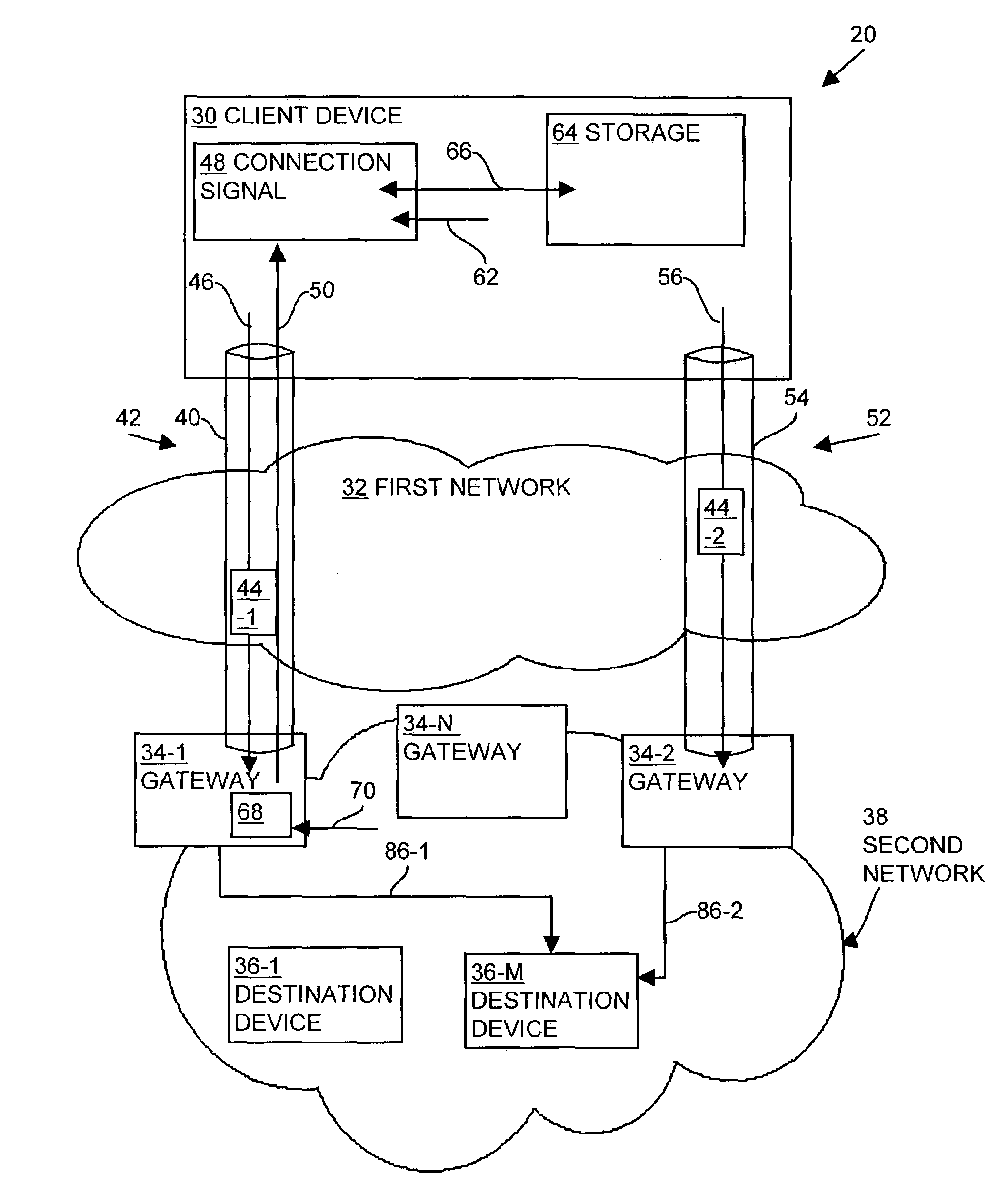
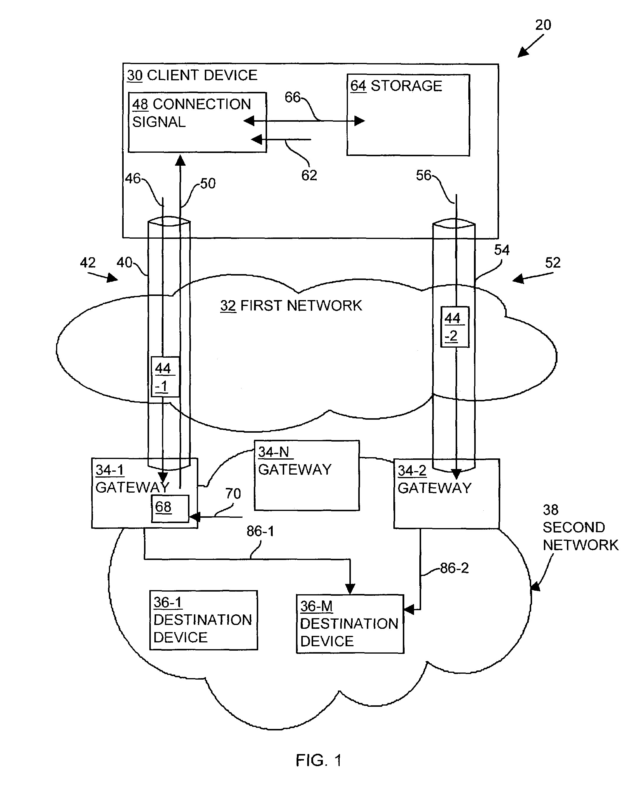
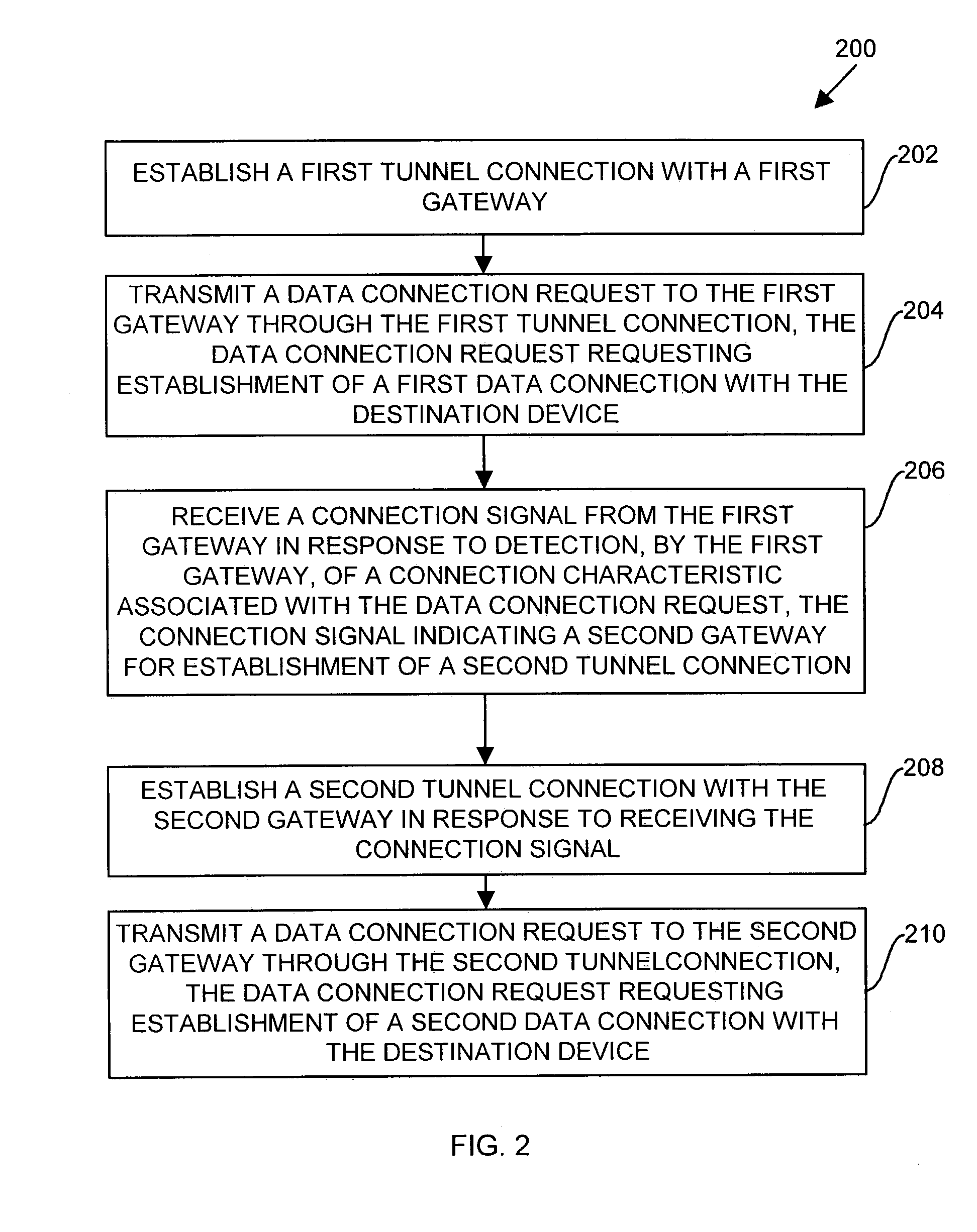
[0004]By contrast, embodiments of the present invention significantly overcome such deficiencies and provide methods and apparatuses for load balancing tunnels to a private network to maximize data transmission performance while also endeavoring to reduce traffic transmission burden (and associated cost) within the private network. Generally, in operation, a client device establishes an initial or first tunnel or tunnel connection (e.g., a VPN connection), through a public network, with a first gateway (e.g., a VPN gateway) of a private network and establishes, through the tunnel, a data connection with a destination device within the private network. The first gateway monitors, analyzes, or otherwise has knowledge of the geographic locations of the gateways associated with the private network relative to the geographic location of the destination device associated with the data connection. Based upon such monitoring, the first gateway transmits information to the client device relating to establishment of a second tunnel with a second or preferred gateway of the private network. The client device then establishes the second tunnel connection (e.g., a VPN tunnel) with the second gateway and establishes a data connection with the destination device through the second gateway. By establishing the second tunnel connection with the second gateway, the client device utilizes the bandwidth of the public network to exchange data with the destination device, thereby decreasing data transmission burden and associated costs to the private network and potentially improving performance of the connection depending on the characteristics of the public and private portion of traffic traversal.
[0005]In other words, in conventional VPN systems, a user is often presented with a list of various VPN gateways that that user may select to connect to a corporate network and the user often chooses the VPN gateway that is physically closest to the user. This is due in part to the intuitive nature of users who feel compelled to couple to the corporate network at the closest point possible to the relative location of that user to either minimize connection costs (e.g., to avoid long distance charges if dialing in) or to minimize security risks of having to couple to the corporate network via a gateway remotely located from the user. Embodiments of the invention operate to optimize the overall total network path for communications between the client device and the destination (via the gateway) through the use of different gateways (e.g., and different tunnels from the client to those gateways) for traffic of differing types, or having varying destinations, within the private network. Selection of an “appropriate” VPN gateway for particular traffic flows involving the client device involves the optimization of some performance criterion or combination of performance criteria, such as latency, throughput, internal network cost, and external network cost.

Problems solved by technology

Conventional techniques that provide for user selection of a virtual private network gateway suffer from a variety of deficiencies.
In such a case, the user maximizes the consumed bandwidth within the corporate network, thereby increasing the cost of data distribution or transmission to the corporation.
In some case, selection of a VPN gateway close to the client can also increase the latency of the connection, as experienced by the user.

Method used


Image

  • Methods and apparatus for establishing a computerized device tunnel connection
  • Methods and apparatus for establishing a computerized device tunnel connection
  • Methods and apparatus for establishing a computerized device tunnel connection

Examples


Embodiment Construction

[0027]Embodiments of the present invention provide methods and apparatuses for load balancing tunnels to a private network to provide relatively high data transmission performance while reducing traffic cost within the private network. A client device establishes a first tunnel connection, through a public network, with a first gateway of a private network and establishes, through the tunnel, a data connection with a destination device within the private network. The first gateway monitors or analyzes the geographic locations of the gateways associated with the private network relative to the geographic location of the destination device associated with the data connection. Based upon such monitoring, the first gateway transmits information to the client device relating to establishment of a second tunnel connection with a second gateway of the private network. The client device establishes the second tunnel connection with the second gateway and establishes a data connection with t...


PUM


Abstract

A client device establishes a first tunnel connection or tunnel, through a public network, with a first gateway of a private network and establishes, through the tunnel connection, a data connection with a destination device within the private network. The first gateway monitors or analyzes the geographic locations of the gateways associated with the private network relative to geographic location of the destination device associated with the data connection. Based upon such the monitoring, the first gateway transmits information to the client device relating to establishment of a second tunnel connection or tunnel with a second gateway of the private network. The client device establishes the second tunnel connection with the second gateway and establishes a data connection with the destination device through the second gateway. By establishing the second tunnel connection with the second gateway, the client device utilizes the bandwidth of the public network to exchange data with the destination device, thereby decreasing data transmission costs to the private network and decreasing private network latency.

Description

BACKGROUND OF THE INVENTION[0001]A computer network, such as the Internet, allows users operating client computer systems to transmit data to and receive data from one or more sites or servers across the network. One conventional form of data transmission involves the use of a virtual private network (VPN) within the computer network. One type of VPN involves a private network constructed using a public network infrastructure (e.g., the Internet) to securely connect divergent network nodes (e.g., remote sites or users). Instead of using a dedicated, physical connection, such as a leased line, a VPN uses “virtual” connections routed from, for example, a company's private central network through a public network (e.g., the Internet) to a remote site or to a remote employee on the road or working from home. Such “virtual” connections are formed in a process known as tunneling. Such VPN's are conventionally constructed to operate over a public network through the use of a combination of...

Claims


Application Information

Patent Timeline
Patent Type & Authority Patents(United States)
IPC IPC(8): G06F15/173G06F15/16H04L12/26
CPCH04L12/4633H04L12/66
Inventor O'TOOLE, JR., JAMES W.TOWNSLEY, WILLIAM MARK
Owner CISCO TECH INC
Learn More