
Field sequential display device having longer black insertion period and a plurality of display areas

a display device and black insertion period technology, applied in the field of display devices, can solve the problems of preventing the improvement of moving image performance, and achieve the effect of superior display quality easily

Inactive Publication Date: 2014-01-07
SHARP KK
View PDF4 Cites 3 Cited by
  • Summary
  • Abstract
  • Description
  • Claims
  • Application Information

AI Technical Summary

Benefits of technology

The present invention is about improving the performance of moving images on a display device. It achieves this by using a backlight with multiple light sources that emit different colors. These light sources are switched on in a specific order to create a superior display quality. The timing of the light sources is controlled so that there is no interference between them, and the display device can show longer periods of black insertion. This invention results in a display device that is easy to drive and has superior display quality.

Problems solved by technology

However, in the conventional liquid crystal display device as described above, the black insertion is not taken into consideration, which prevents the improvement of the moving image performance.

Method used


Image

  • Field sequential display device having longer black insertion period and a plurality of display areas
  • Field sequential display device having longer black insertion period and a plurality of display areas
  • Field sequential display device having longer black insertion period and a plurality of display areas

Examples


Embodiment Construction

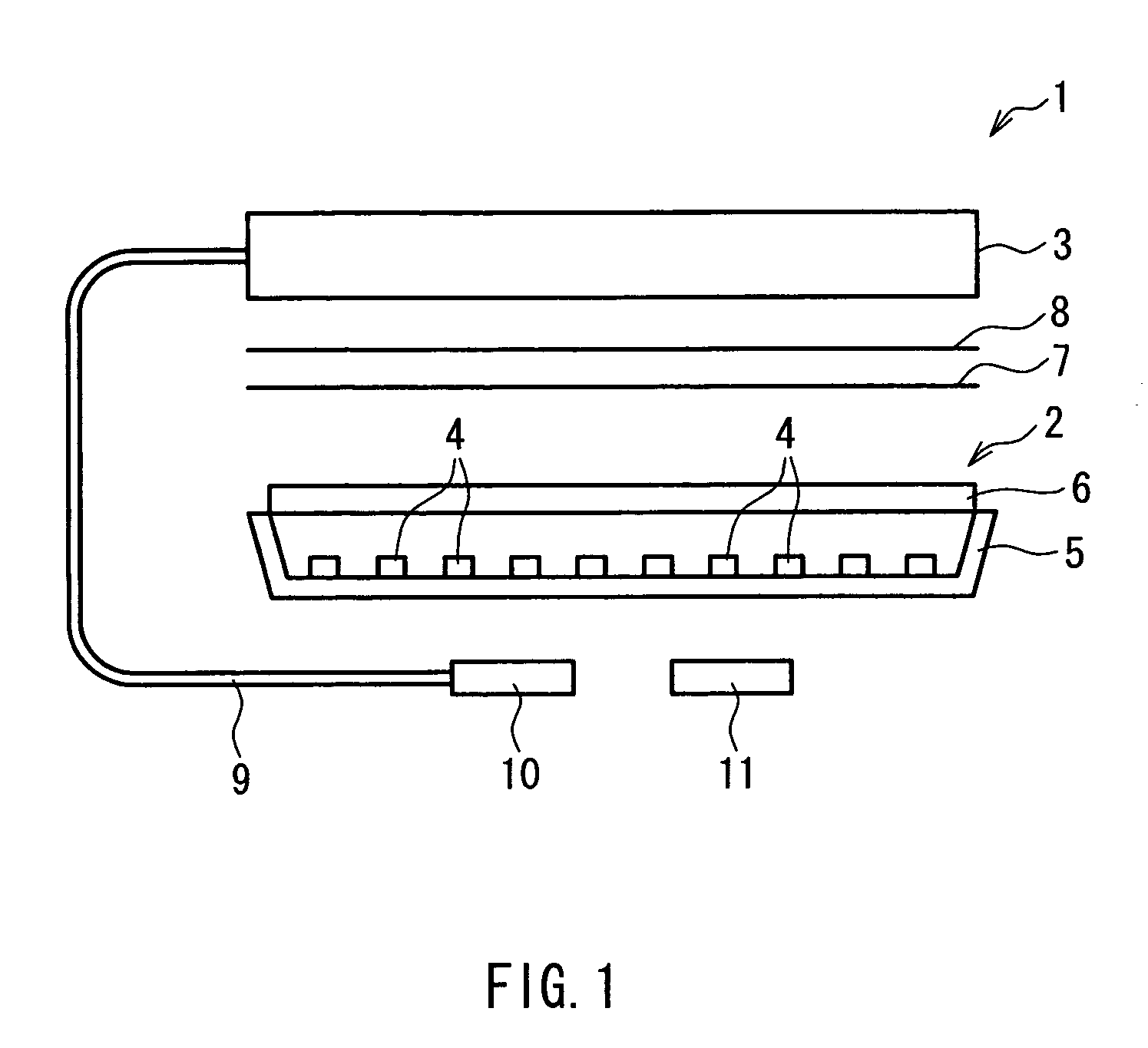
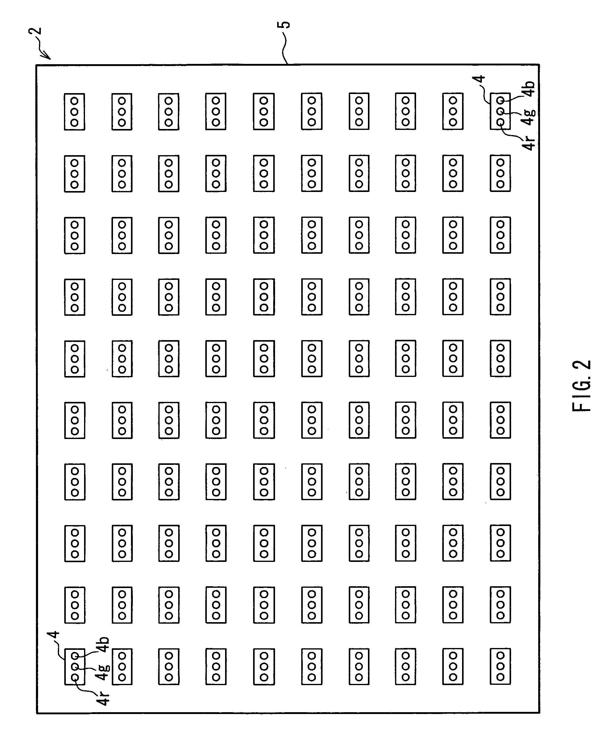
[0030]Hereinafter, a preferred embodiment of a display device of the present invention will be described with reference to drawings. In the following description, the case where the present invention is applied to a transmission-type liquid crystal display device will be described. Further, the dimensions of constituent members in the drawings do not faithfully reflect the actual dimensions of constituent members, dimension ratio of the respective constituent members, etc.

[0031]FIG. 1 is a view illustrating a liquid crystal display device according to one embodiment of the present invention, and FIG. 2 is a plan view showing a configuration of main portions of a backlight device shown in FIG. 1. In FIGS. 1 and 2, a liquid crystal display device 1 of the present embodiment includes a backlight device 2 as a backlight portion and a liquid crystal panel 3 as a display portion for displaying information, which is illuminated by light from the backlight device 2. In the present embodimen...


PUM


Abstract

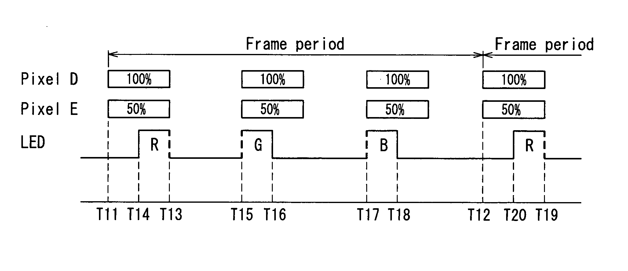
A plurality of display areas are provided in a liquid crystal panel (display portion) and a plurality of illumination areas respectively allowing light from light-emitting diodes (light sources) to be incident upon the plurality of display areas are set in a backlight device (backlight portion). Further, light-emitting diodes of RGB (a plurality of colors) are provided per illumination area. In the light-emitting diodes of RGB, a reference point of start of lighting of the light-emitting diode to be switched on lastly in a frame period is set so as to coincide with a beginning point of a lighting period of the light-emitting diode, and a reference point of start of lighting of the light-emitting diode to be switched on firstly in the frame period is set so as to coincide with an end point of the lighting period of the light-emitting diode.

Description

BACKGROUND OF THE INVENTION[0001]1. Field of the Invention[0002]The present invention relates to a display device, and in particular, to a non-light-emitting display device such as a liquid crystal display device.[0003]2. Description of Related Art[0004]Recently, for example, liquid crystal display devices have been used widely in liquid crystal televisions, monitors, and mobile telephones, as flat panel displays having features such as thinness and light weight, compared with conventional Braun tubes. Such a liquid crystal display device includes a backlight device emitting light and a liquid crystal panel displaying a desired image by playing a role of a shutter with respect to light from light sources provided in the backlight device.[0005]Further, in the above-described conventional liquid crystal display device, for example, JP 2006-220685 A has proposed the following: with respect to a liquid crystal panel not provided with color filters, a driving method (so-called field sequ...

Claims


Application Information

Patent Timeline
Patent Type & Authority Patents(United States)
IPC IPC(8): G09G3/36
CPCG09G2320/0646G09G2310/0235G09G2320/0686G09G3/3413G09G2360/16G09G2320/0209G09G3/3648
Inventor UEHARA, KAZUHIRO
Owner SHARP KK
Learn More