Industrial robot

a robot and industrial technology, applied in the field of industrial robots, can solve the problems of limiting application in a narrow place, affecting the operation of the robot,

Active Publication Date: 2014-01-21
DAIHEN CORP +1
View PDF40 Cites 36 Cited by
  • Summary
  • Abstract
  • Description
  • Claims
  • Application Information

AI Technical Summary

Benefits of technology

[0009]In view of the above point, an object of the present invention is to provide an industrial robot which can prevent interference of a flow path for supplying gas to a tool mounting portion with an external structure.
[0011]According to the industrial robot having the above construction, the gas supplied to the flow path is supplied from the robot base to the tool mounting portion through the interiors of the rotation frame, the tube, the shoulder, the swing arm and the tool mounting rotation arm without the flow path being exposed to the outside. Thus, interference of the flow path with an external structure such as a work can be prevented, wherefore adaptability to a narrow place or the like can be improved and the gas can be reliably supplied to the tool mounting portion.

Problems solved by technology

However, if the pipe is located at an outer side of the arm near the wrist portion in the industrial robot as disclosed in patent literature 1, the pipe may interfere with an external structure and may be broken in some cases.
Further, the pipe may be entangled around an external structure and may become unable to supply air.
However, if a large space is taken for the pipe path, an area around the rotating shaft of the arm becomes larger, thereby limiting application in a narrow place or the like.

Method used


Image

  • Industrial robot
  • Industrial robot
  • Industrial robot

Examples


Embodiment Construction

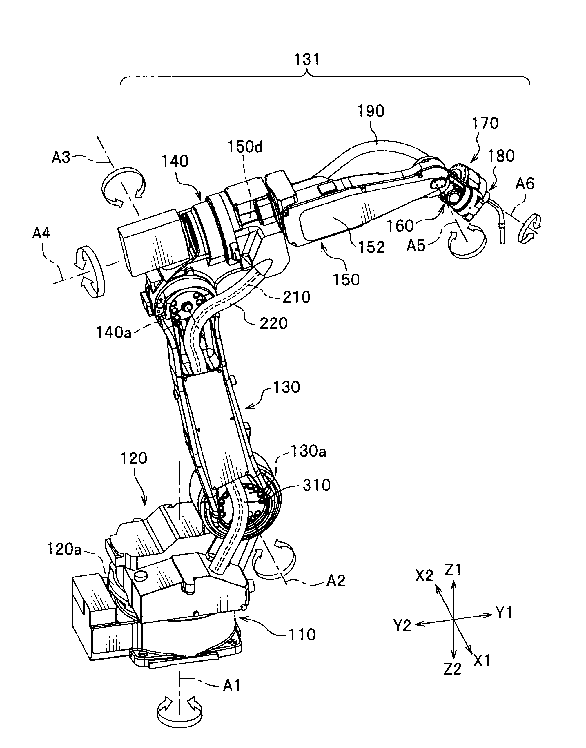
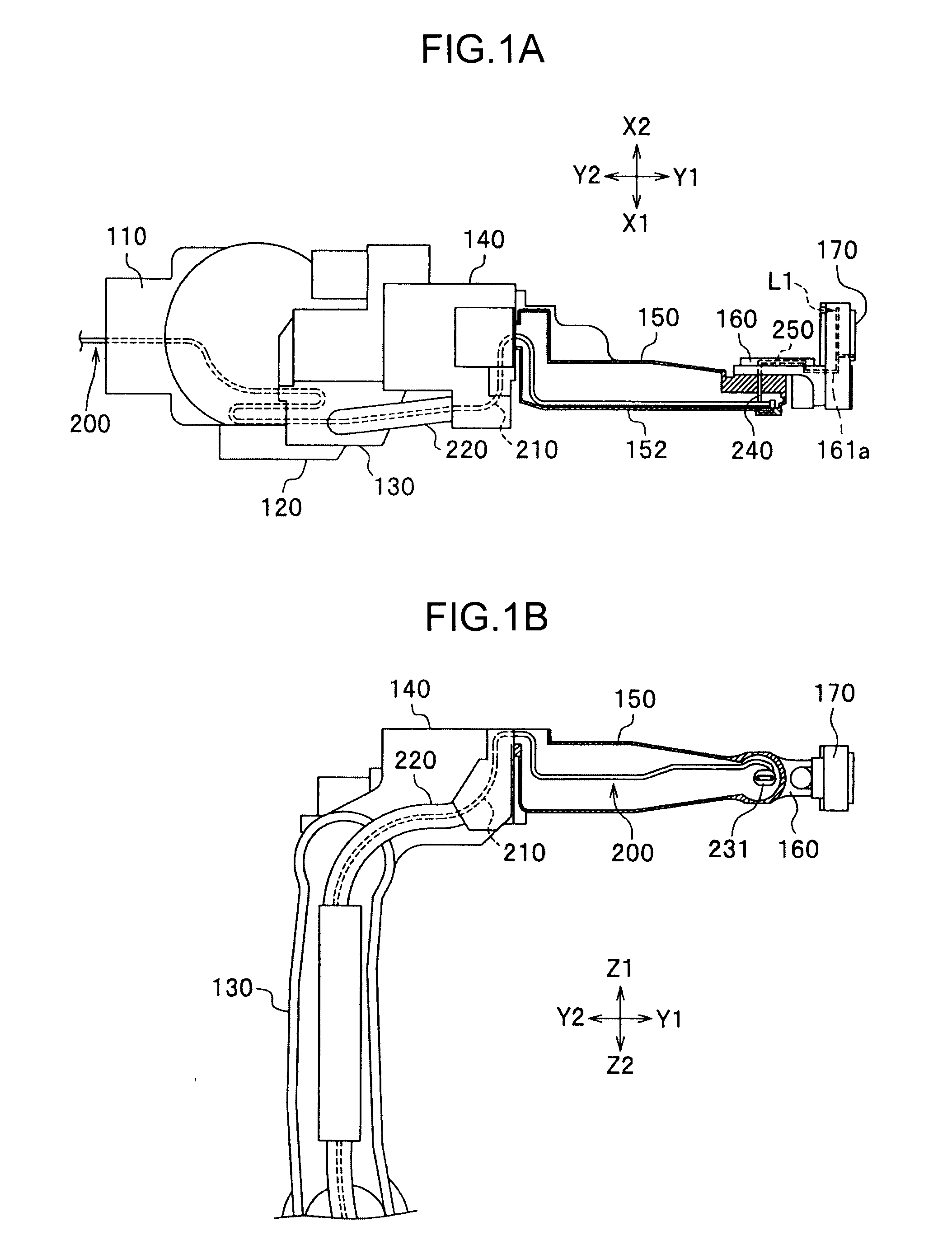
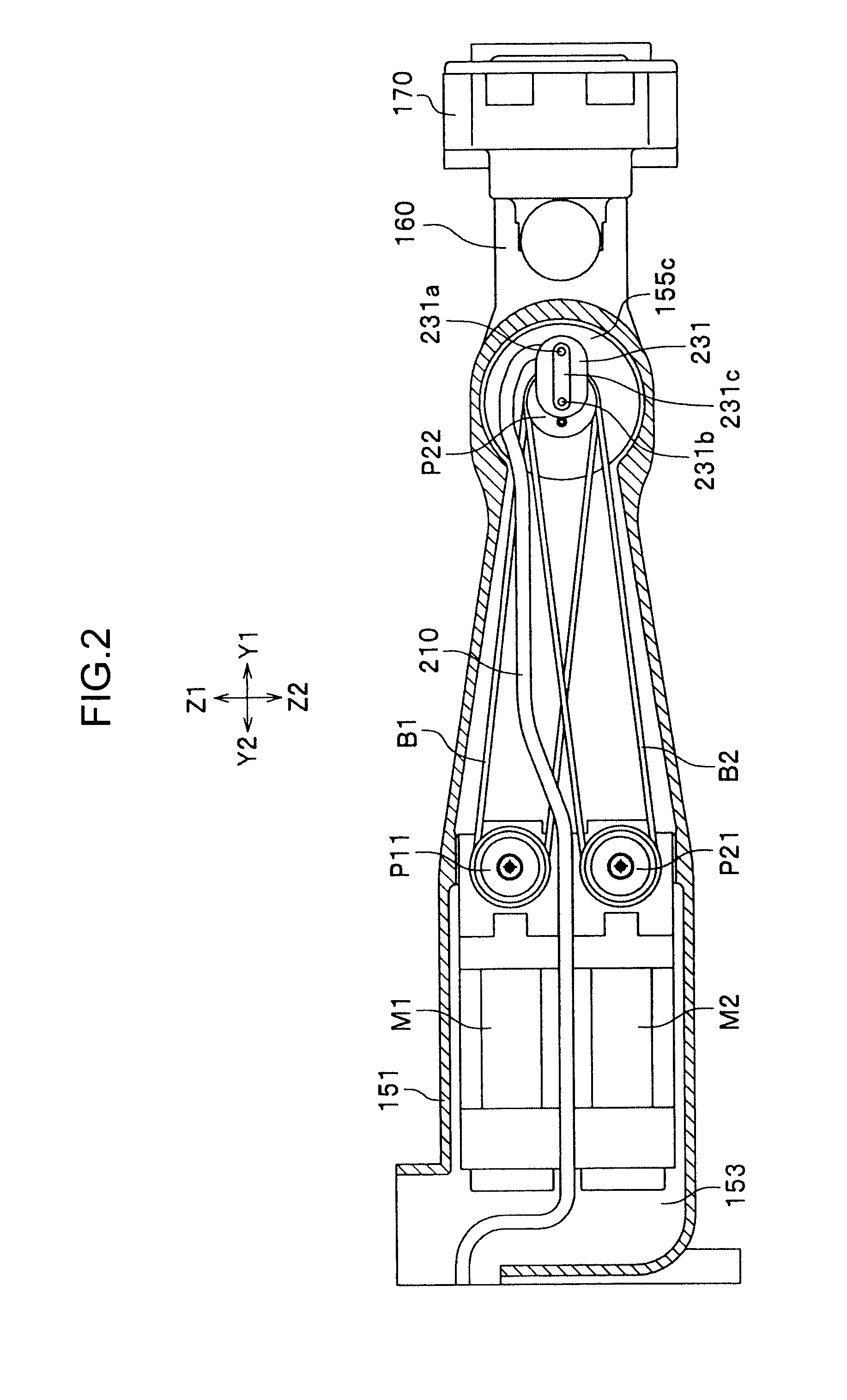
[0022]Hereinafter, an overall external construction of an industrial robot 10 according to the present invention is described with reference to FIGS. 7 and 8.

[0023]In the following description, terms “one end” and “other end” are used. “One end” basically means an upstream end in a structure extending from a robot base 110 (called an upstream side) of the industrial robot 100 to a tool 180 (called a downstream side) detachably mounted to a tool mounting portion 170 by way of a rotation frame 120, a lower arm 130, a shoulder 140, a swing arm 150 and a tool mounting rotation arm 160. “Other end” means a downstream end of a target constituent element.

[0024]The industrial robot 100 of this embodiment is a so-called six-axis articulated welding robot and includes the robot base 110 fixed to a mounting surface, the rotation arm 120 which rotates about a first axis A1 on the robot base 110, the lower arm 130 which is connected to the rotation arm 120 and rotates about a second axis A2, and...


PUM


Abstract

The present invention is characterized by arranging a flow path 200 for supplying driving gas to a tool mounting portion 170 from a robot base 110 to the tool mounting portion 170 through the interiors of a rotation frame 120, a tube 220, a shoulder 140, a swing arm 150 and a tool mounting rotation arm 160.

Description

BACKGROUND OF THE INVENTION[0001]1. Field of the Invention[0002]The present invention relates to an industrial robot such as an articulated robot for performing an operation by a tool mounted to the tip of an arm.[0003]2. Description of the Related Art[0004]Generally, so-called articulated robots and other robots are widely used as industrial robots such as welding robots. An articulated robot includes a tool mounting portion, to which a tool is to be mounted, at a tip portion and the tool is detachable if necessary. Some of industrial robots of recent years are so constructed that one industrial robot successively performs various operations by itself by automatically exchanging a plurality of types of tools according to a program.[0005]Such an industrial robot includes a locking mechanism for locking a tool and a tool mounting portion to reliably perform operations by preventing detachment of the tool from the tool mounting portion. The locking mechanism is driven, for example, by...

Claims


Application Information

Patent Timeline
Patent Type & Authority Patents(United States)
IPC IPC(8): B25J17/00
CPCB25J19/0029Y10T74/20311B25J9/06B25J19/00
Inventor NAKAGIRI, HIROSHIYOON, SUNGJAEKONDO, MAKOTOMINATO, TATSUJI
Owner DAIHEN CORP
Why Eureka
Try Eureka