
Method and appartus for transforming a stratigraphic grid

a stratigraphic grid and appartus technology, applied in the field of computerized tools, can solve the problems of less-than-optimal degenerated and/or distorted cells,

Active Publication Date: 2014-01-21
ASPEN PARADIGM HLDG LLC +1
View PDF2 Cites 25 Cited by
  • Summary
  • Abstract
  • Description
  • Claims
  • Application Information

AI Technical Summary

Benefits of technology

The patent describes a way to create a "transformed SGridView" that represents the underground region of the Earth. This is done by moving the vertices (the points) of an input stratigraphic grid. The technical effect of this invention is a better understanding of the complex structure of the underground landscape, which can aid in energy production, mineral mining, and other applications.

Problems solved by technology

For example, these tools may incorrectly model “dying faults,” they may produce an inaccurate geological model in the presence of faults intersecting each other in an “Y” or “X” manner, or they may produce degenerated and / or distorted cells.
When simulating flow via through a geological terrain represented by one of these conventional stratigraphic grids, these degenerated and / or distorted cells may yield less-than-optimal results.

Method used


Image

  • Method and appartus for transforming a stratigraphic grid
  • Method and appartus for transforming a stratigraphic grid
  • Method and appartus for transforming a stratigraphic grid

Examples


Embodiment Construction

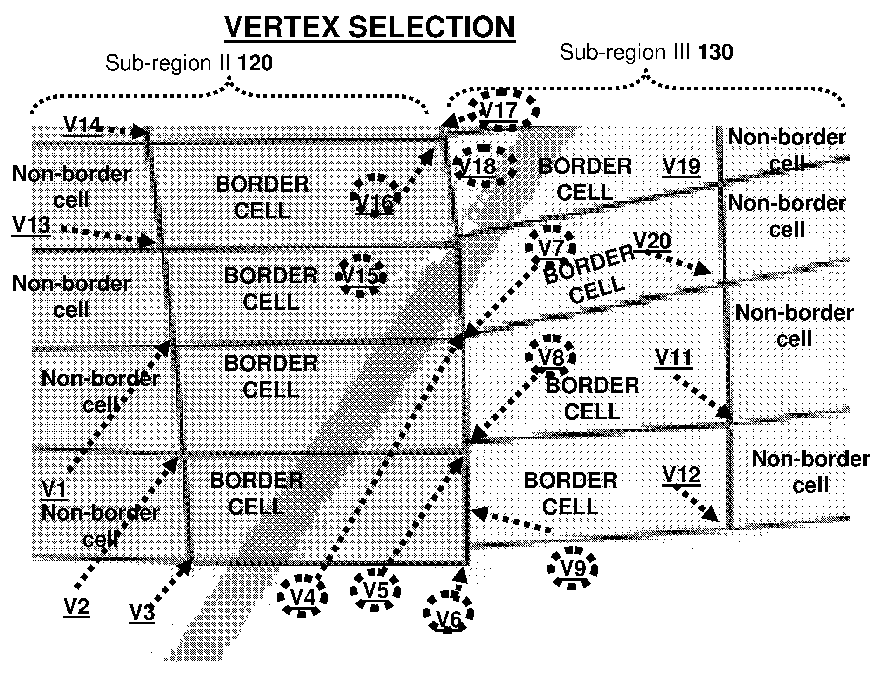
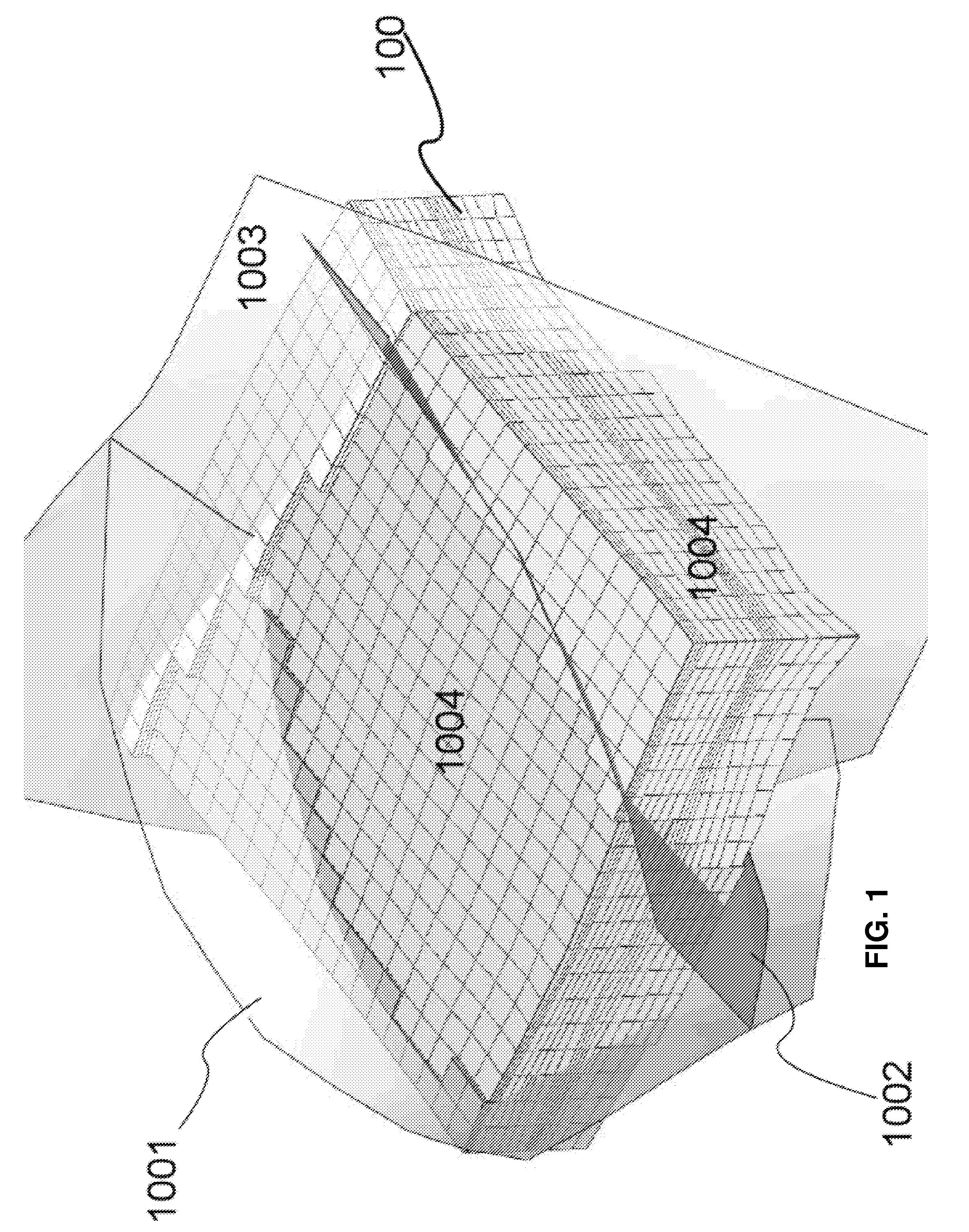
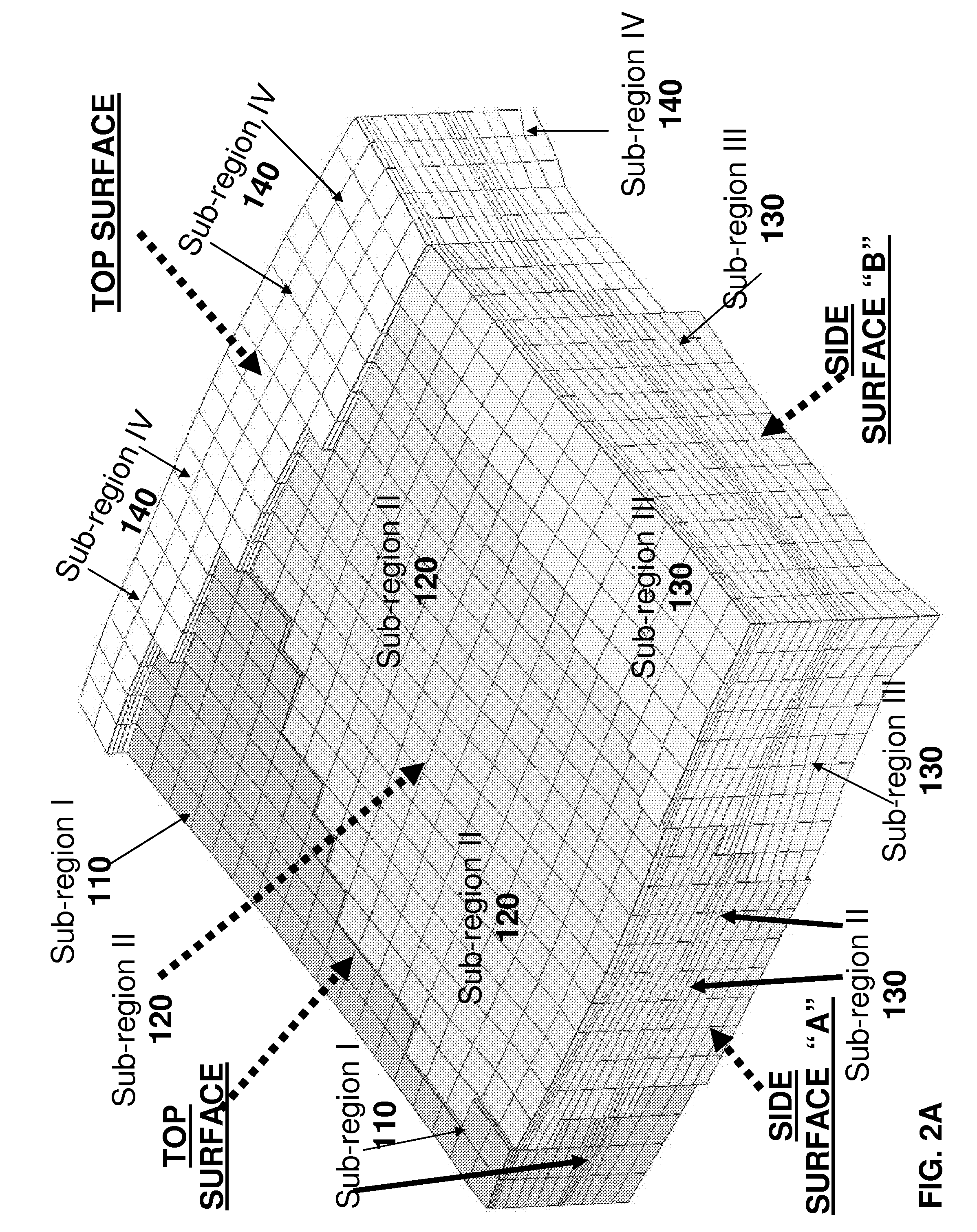
[0033]A method of transforming an input stratigraphic grid SGrid which represents a region including one or more geological discontinuities is now disclosed. The method comprises: for at least one target cell that is local to one or more geological discontinuities, the target cell being selected from the group consisting of: i) a divided cell that is divided by one or more of the geological-discontinuities; and ii) a bordering cell that borders one or more the geological-discontinuities and / or one or more of the divided cells, transforming the target cell by displacing at least one target vertex of the target cell of the input SGrid in a selected direction that: i) is selected to approximate a local tangent of the reference horizon; and ii) is oriented from the target vertex to a representative manifold representing one of the geological discontinuities and / or an intersection between two or more of the geological discontinuities, wherein a magnitude of a displacement by which the ta...


PUM


Abstract

A method of transforming an input stratigraphic grid SGrid which represents a region including one or more geological discontinuities is now disclosed. At least one target cell that is local to one or more geological discontinuities is transformed by displacing at least one target vertex of the target cell of the input SGrid in a selected direction that: i) is selected to approximate a local tangent of the reference horizon; and ii) is oriented from the target vertex to a representative manifold representing one of the geological discontinuities and / or an intersection between two or more of the geological discontinuities. A magnitude of a displacement by which the target vertex is moved is determined according to a non-Euclidian distance between the target vertex of the target cell of the input SGrid and the representative manifold.

Description

FIELD OF THE INVENTION[0001]The present invention relates to computerized tools for creating digital models of the Earth's subsurface.BACKGROUND OF THE INVENTION[0002]There is an ongoing need for improved computerized tools which facilitate the locating of new oil and natural gas reservoirs, the optimizing of production from new and existing reservoirs, and for other related geological applications. Some embodiments of the present invention relate to stratigraphic grids (SGrids) that provide a stair-stepped approximation of a geological discontinuity. One technique for producing such an SGrid is disclosed in US 2008 / 0243454, of one of the present inventors.[0003]As was discussed in the background section of US 2008 / 0243454, incorporated herein by reference in its entirety, many conventional tools for generating a stratigraphic grid suffer a number of drawbacks. For example, these tools may incorrectly model “dying faults,” they may produce an inaccurate geological model in the prese...

Claims


Application Information

Patent Timeline
IPC IPC(8): G06G7/48
CPCG06T17/00G06T17/20G06T17/05G06G7/48
Inventor MALLET, JEAN-LAURENTLI, WAN-CHIUDULAC, JEAN-CLAUDE
Owner ASPEN PARADIGM HLDG LLC
Learn More