Steerable leaky wave antenna capable of both forward and backward radiation

a leaky wave antenna and forward radiation technology, applied in leaky waveguide antennas, antennas, electrically short antennas, etc., can solve the problems of inability to direct radiation toward the zenith or close to the horizon, limited steering range of the antenna, and inability to backward leaky wave radiation

Active Publication Date: 2006-07-04
HRL LAB
View PDF191 Cites 82 Cited by
  • Summary
  • Abstract
  • Description
  • Claims
  • Application Information

AI Technical Summary

Problems solved by technology

However, in the previous disclosures, it was not disclosed how to produce backward leaky wave radiation, and therefore the steering range of the

Method used


Image

  • Steerable leaky wave antenna capable of both forward and backward radiation
  • Steerable leaky wave antenna capable of both forward and backward radiation
  • Steerable leaky wave antenna capable of both forward and backward radiation

Examples


Embodiment Construction

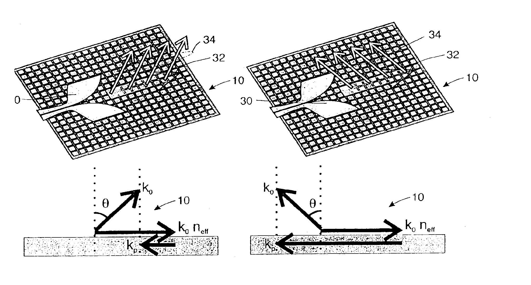
[0045]The new beam steering technology disclosed herein can be summarized, in one aspect, by the following statement: The impedance of the tunable impedance surface 10 is tuned in a non-uniform manner to create an impedance function across the surface, so that when a wave 32 is launched across the surface, it is scattered by this impedance function to a desired radiation angle. Typically, impedance function is periodic or nearly periodic. This can be thought of as being equivalent to a microwave grating, where the surface waves are scattered by the grating into a direction that is determined by phase matching on the surface. The radiation angle is determined by the difference between the wave vector along the surface, and the wave vector that describes the periodic impedance function, as shown in FIG. 6.

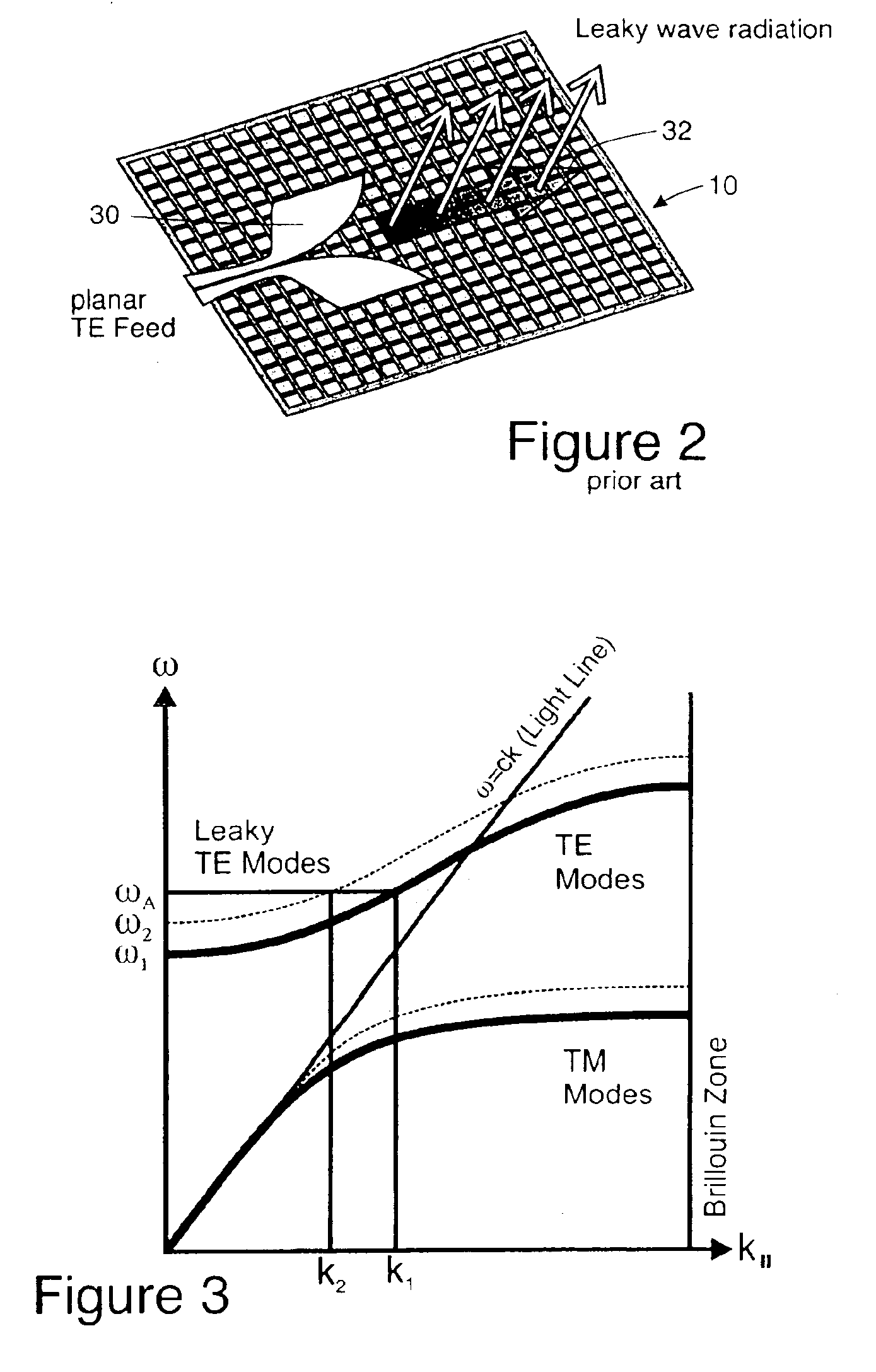
[0046]From another point of view or aspect, the band structure of the tunable impedance surface 10 is folded in upon itself, because the period of the surface has been increased to t...


PUM


Abstract

Leaky wave antenna beam steering that is capable of steering in a backward direction, as well as further down toward the horizon in the forward direction than was previously possible, and also directly toward zenith. The disclosed antenna and method involve applying a non-uniform impedance function across a tunable impedance surface in order to obtain such leaky wave beam steering.

Description

CROSS REFERENCE TO RELATED APPLICATIONS AND PATENTS[0001]This application claims the benefits of U.S. Provisional Applications Nos. 60 / 470,028 and 60 / 479,927 filed May 12, 2003 and Jun. 18, 2003, respectively, the disclosures of which are hereby incorporated herein by reference.[0002]This application is related to the disclosures of U.S. Provisional Patent Application Ser. No. 60 / 470,027 filed May 12, 2003 entitled “Meta-Element Antenna and Array” and its related non-provisional application No. 10 / 792,411 filed on the day as this application and assigned to the owner of this application, both of which are hereby incorporated by reference.[0003]This application is related to the disclosures of U.S. Pat. Nos. 6,496,155; 6,538,621 and 6,552,696 all to Sievenpiper et al., all of which are hereby incorporated by reference.TECHNICAL FIELD[0004]This disclosure describes a low-cost, electronically steerable leaky wave antenna. It involves several parts: (1) An electronically tunable impedan...

Claims


Application Information

Patent Timeline
IPC IPC(8): H01Q9/00H01Q15/02H01Q13/20H01Q21/06H01Q23/00
CPCH01Q13/20H01Q21/061H01Q15/008H01Q15/0066H01Q23/00
Inventor SIEVENPIPER, DANIEL F.
Owner HRL LAB
Why Eureka
Try Eureka