Non-linear dynamic predictive device

a dynamic prediction and non-linear technology, applied in adaptive control, process and machine control, instruments, etc., can solve the problems of over-parameterization of models, exponential growth of parameters to be identified, and over-parameterization problem exacerbated, etc., to achieve the effect of sufficient accuracy

Inactive Publication Date: 2002-09-17
ASPENTECH CORP
View PDF3 Cites 83 Cited by
  • Summary
  • Abstract
  • Description
  • Claims
  • Application Information

AI Technical Summary

Benefits of technology

The importance of this invention is that its structure is shown to be able to approximate a large class of non-linear processes (any discrete, causal, time invariant, nonlinear multi-input/single output (MISO) process...

Problems solved by technology

These approaches result in over-parameterization of the models (Qin and Badgwell, 1996).
This over-parameterization problem is exacerbated for non-linear models since standard non-parametric approaches, such as Volterra series, lead to an exponential growth in the number of parameters to be identified.
Though NARX models are found in many case-studies, a problem with NARX models using feed forward neural networks is that they offer only short-term predictions (Su, et al, 1992).
Recurrent neural networks with internal or external feedback connections provide a better solution to the long-term prediction problem, but training such models is very...

Method used


Image

  • Non-linear dynamic predictive device
  • Non-linear dynamic predictive device
  • Non-linear dynamic predictive device

Examples


Embodiment Construction

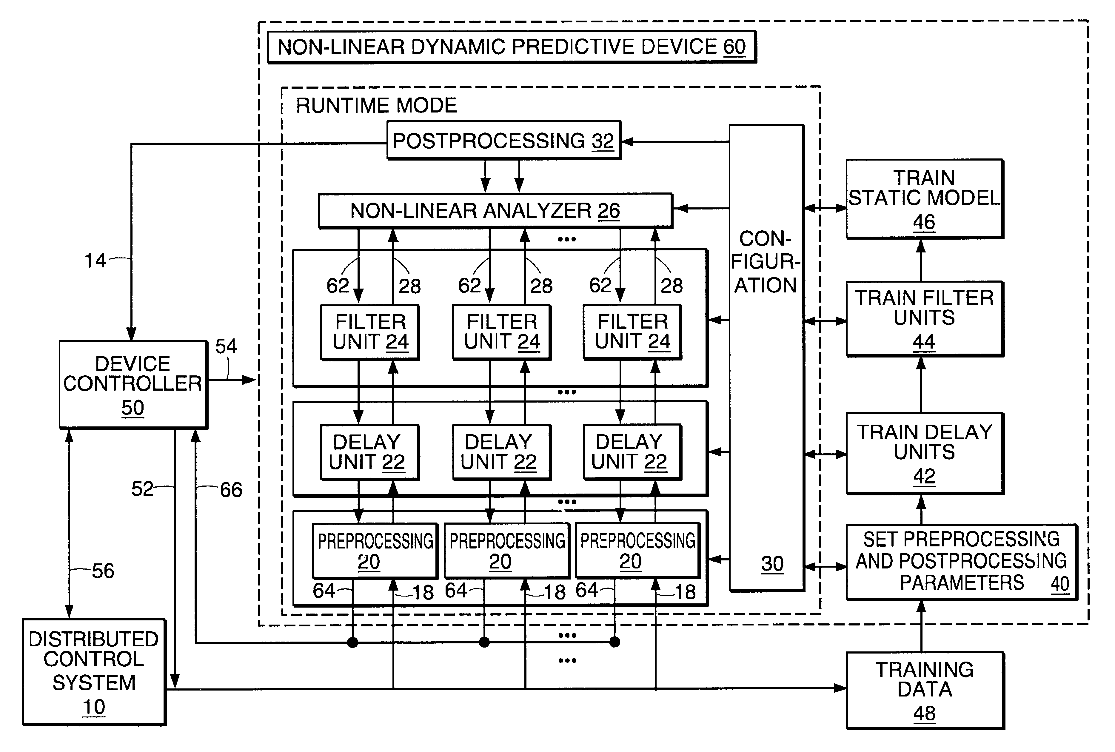
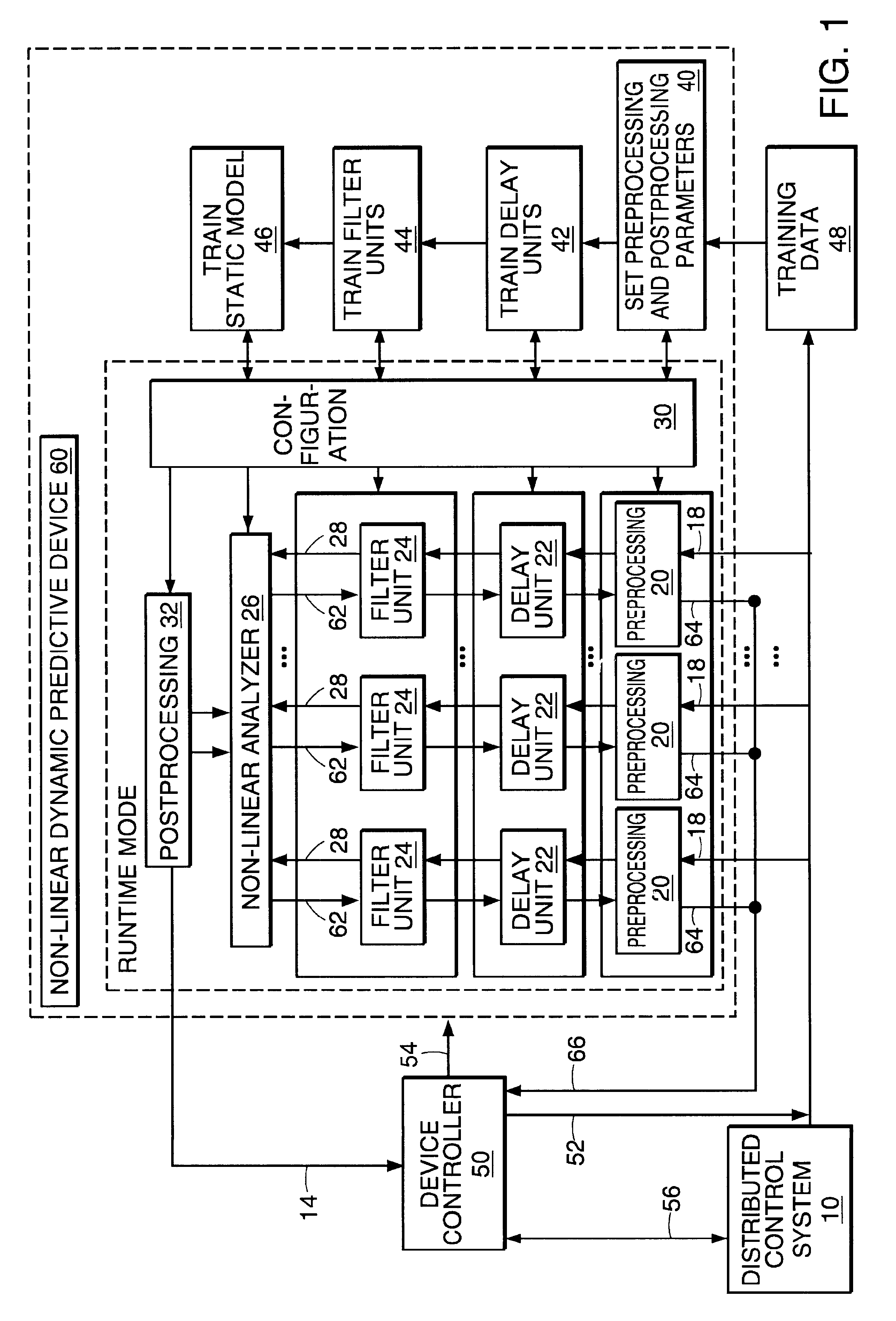
FIG. 1 is an overall block diagram of the invention and its context. An external device controller (50) synchronizes the flow of data to and from the predictive device via the data paths (18), (14), and (64). The device controller also controls the mode of operation and the path stepping of the predictive device via the control path (54). The external device controller may also communicate with a DCS (10) or other data / control system both for requesting data and for requesting control changes to the modeled process; however the exact external context and configuration of the device controller is beyond the scope of this application.

V.1 Forward Runtime Operation of the Prediction Device

The figures and equations in this detailed description refer to an index k that represents a data point in a sequence of data points. This index has different meanings depending on whether the forward operational mode of the device is prediction mode or horizon mode.

In prediction mode data is provided ...


PUM


Abstract

A non-linear dynamic predictive device (60) is disclosed which operates either in a configuration mode or in one of three runtime modes: prediction mode, horizon mode, or reverse horizon mode. An external device controller (50) sets the mode and determines the data source and the frequency of data. In prediction mode, the input data are such as might be received from a distributed control system (DCS) (10) as found in a manufacturing process; the device controller ensures that a contiguous stream of data from the DCS is provided to the predictive device at a synchronous discrete base sample time. In prediction mode, the device controller operates the predictive device once per base sample time and receives the output from the predictive device through path (14). In horizon mode and reverse horizon mode, the device controller operates the predictive device additionally many times during base sample time interval. In horizon mode, additional data is provided through path (52). In reverse horizon mode data is passed in a reverse direction through the device, utilizing information stored during horizon mode, and returned to the device controller through path (66). In the forward modes, the data are passed to a series of preprocessing units (20) which convert each input variable (18) from engineering units to normalized units. Each preprocessing unit feeds a delay unit (22) that time-aligns the input to take into account dead time effects such as pipeline transport delay. The output of each delay unit is passed to a dynamic filter unit (24). Each dynamic filter unit internally utilizes one or more feedback paths that are essential for representing the dynamic information in the process. The filter units themselves are configured into loosely coupled subfilters which are automatically set up during the configuration mode and allow the capability of practical operator override of the automatic configuration settings. The outputs (28) of the dynamic filter units are passed to a non-linear analyzer (26) which outputs a value in normalized units. The output of the analyzer is passed to a post-processing unit (32) that converts the output to engineering units. This output represents a prediction of the output of the modeled process. In reverse horizon mode, a value of 1 is presented at the output of the predictive device and data is passed through the device in a reverse flow to produce a set of outputs (64) at the input of the predictive device. These are returned to the device controller through path (66). The purpose of the reverse horizon mode is to provide essential information for process control and optimization. The precise operation of the predictive device is configured by a set of parameters. that are determined during the configuration mode and stored in a storage device (30). The configuration mode makes use of one or more files of training data (48) collected from the DCS during standard operation of the process, or through structured plant testing. The predictive device is trained in four phases (40, 42, 44, and 46) correspo

Description

I. FIELD OF THE INVENTIONThe present invention pertains to a predictive device that models the dynamic input / output relationships of a physical process, particularly in the process industries such as hydrocarbons, polymers, pulp and paper, and utilities. The predictive device is primarily for multivariable process control, but is also applicable to dynamic process monitoring, or to provide a continuous stream of inferred measurements in place of costly or infrequent laboratory or analyzer measurements.II. BACKGROUND OF THE INVENTIONMost existing industrial products designed for multivariable model predictive control (MPC) employ linear step-response models or finite impulse response (FIR) models. These approaches result in over-parameterization of the models (Qin and Badgwell, 1996). For example, the dynamics of a first order single input / single output SISO process which can be represented with only three parameters (gain, time constant and dead-time) in a parametric form typically ...

Claims


Application Information

Patent Timeline
IPC IPC(8): G05B13/04G05B23/02G05B17/02G05B17/00
CPCG05B13/048G05B17/02
Inventor ZHAO, HONGSENTONI, GUILLERMOGUIVER, JOHN P.
Owner ASPENTECH CORP
Why Eureka
Try Eureka