Method and device for setting demodulation reference signals in wireless communication system
a reference signal and wireless communication technology, applied in the field of communication, can solve the problems of receiving interference and being unable to estimate the condition of a channel inside a resource block, and achieve the effect of small system overhead
- Summary
- Abstract
- Description
- Claims
- Application Information
AI Technical Summary
Benefits of technology
Problems solved by technology
Method used
Image
Examples
embodiment 1
[0030](Embodiment 1)
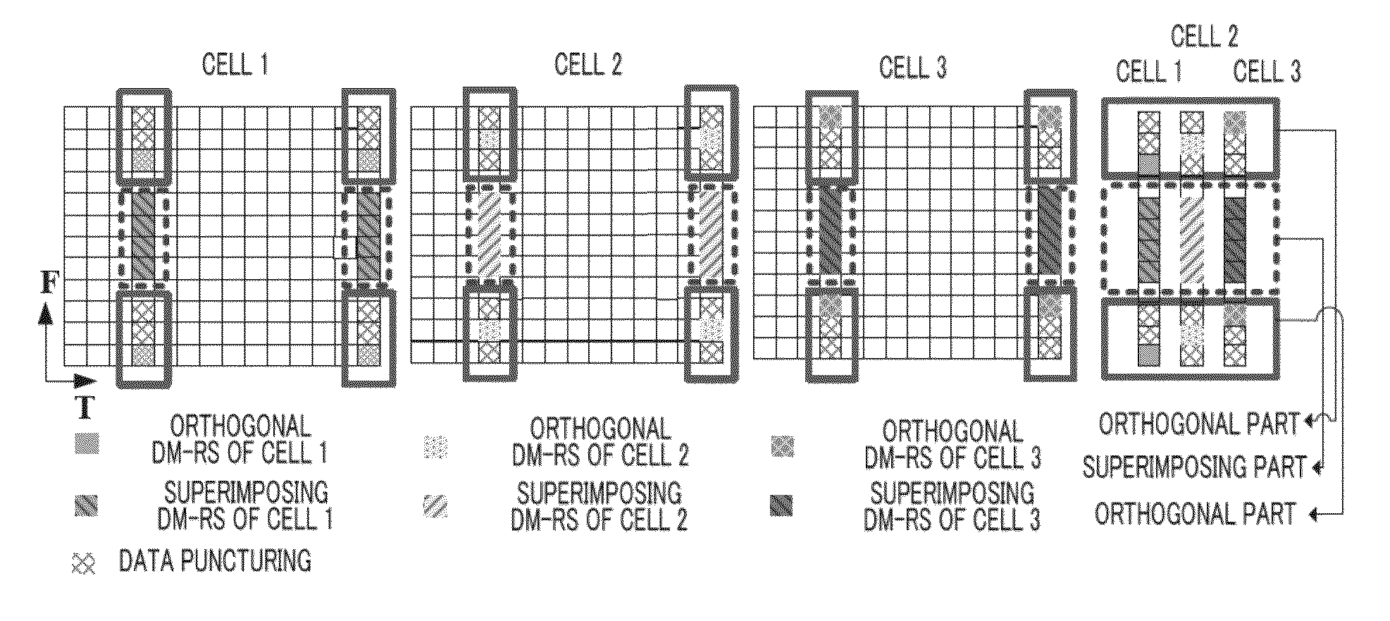
[0031]FIG. 5 shows a situation in which DM-RSs are arranged in resource blocks of three neighboring cells using a DM-RS arrangement method according to Embodiment 1 of the present invention; As shown in FIG. 5, DM-RSs of the respective cells are made up of two parts; an orthogonal part (part in a frame of a solid line in the figure) and a superimposing part (part in a frame of a broken line in the figure). The DM-RSs of the orthogonal part realize orthogonality of DM-RSs among cells through a frequency offset among cells and puncturing of corresponding positions (hereinafter, DM-RS of the orthogonal part will be abbreviated as “orthogonal DM-RS”). The DM-RSs of the superimposing part are not involved in a frequency offset between cells and are arranged at the same positions in a resource block of each cell (hereinafter, the DM-RS in the superimposing part will be abbreviated as “superimposing DM-RS”).
[0032]In FIG. 5, two orthogonal DM-RSs are arranged in two edge...
embodiment 2
[0037](Embodiment 2)
[0038]Embodiment 2 is a modification of Embodiment 1. In Embodiment 2, although DM-RSs can also be divided into orthogonal DM-RSs and superimposing DM-RSs, all these DM-RSs are not arranged in two edge OFDM symbols of a data region of a resource block, but arranged in four OFDM symbols close to edges of the resource block.
[0039]FIG. 7 shows a situation in which DM-RSs are arranged in resource blocks of three neighboring cells using the DM-RS arrangement method according to Embodiment 2 of the present invention. As shown in FIG. 7, orthogonal DM-RSs and superimposing DM-RSs are arranged in two edge OFDM symbols of a data region in a resource block of each cell as in the case of FIG. 5. In addition, orthogonal DM-RSs and superimposing DM-RSs are arranged in available sub-edge OFDM symbols adjacent to these two edge OFDM symbols respectively (the fifth column in the resource block is a reserved region and not used to arrange DM-RSs, and so the sixth column and final...
embodiment 3
[0042](Embodiment 3)
[0043]A case has been described in Embodiments 1 and 2 where DM-RS signals are arranged in a situation in which one resource block only transmits: one-layer data. There is actually a possibility that two-layer data may be transmitted using one resource block. The present embodiment expands the resource block arrangement method in Embodiment 2 of the present invention as shown in FIG. 7 and thereby arranges DM-RSs for a resource block that transmits two-layer data.
[0044]In a situation in which two-layer data is transmitted using one resource block, data of the first layer and data of the second layer are different pieces of data, and so different precoding schemes are used. What is finally transmitted using a data block is a result of coding data of different layers using different precoding schemes and then further superimposing one layer on another. Furthermore, all data of respective layers have their corresponding DM-RSs, which are precoded using the same prec...
PUM
 Abstract
Description
Claims
Application Information
 - R&D
- Intellectual Property
- Life Sciences
- Materials
- Tech Scout
- Unparalleled Data Quality
- Higher Quality Content
- 60% Fewer Hallucinations
Browse by: Latest US Patents, China's latest patents, Technical Efficacy Thesaurus, Application Domain, Technology Topic, Popular Technical Reports.
© 2025 PatSnap. All rights reserved.Legal|Privacy policy|Modern Slavery Act Transparency Statement|Sitemap|About US| Contact US: help@patsnap.com


