Stator for electric rotating machine
a rotating machine and electric technology, applied in the direction of dynamo-electric machines, electrical apparatus, magnetic circuit shapes/forms/construction, etc., can solve the problems of torque ripple and deterioration of steering feeling of the driver, and achieve the effect of suppressing torque ripple of the motor, reducing the resultant magnetic flux, and preventing the distribution of magnetic flux in the motor
- Summary
- Abstract
- Description
- Claims
- Application Information
AI Technical Summary
Benefits of technology
Problems solved by technology
Method used
Image
Examples
first embodiment
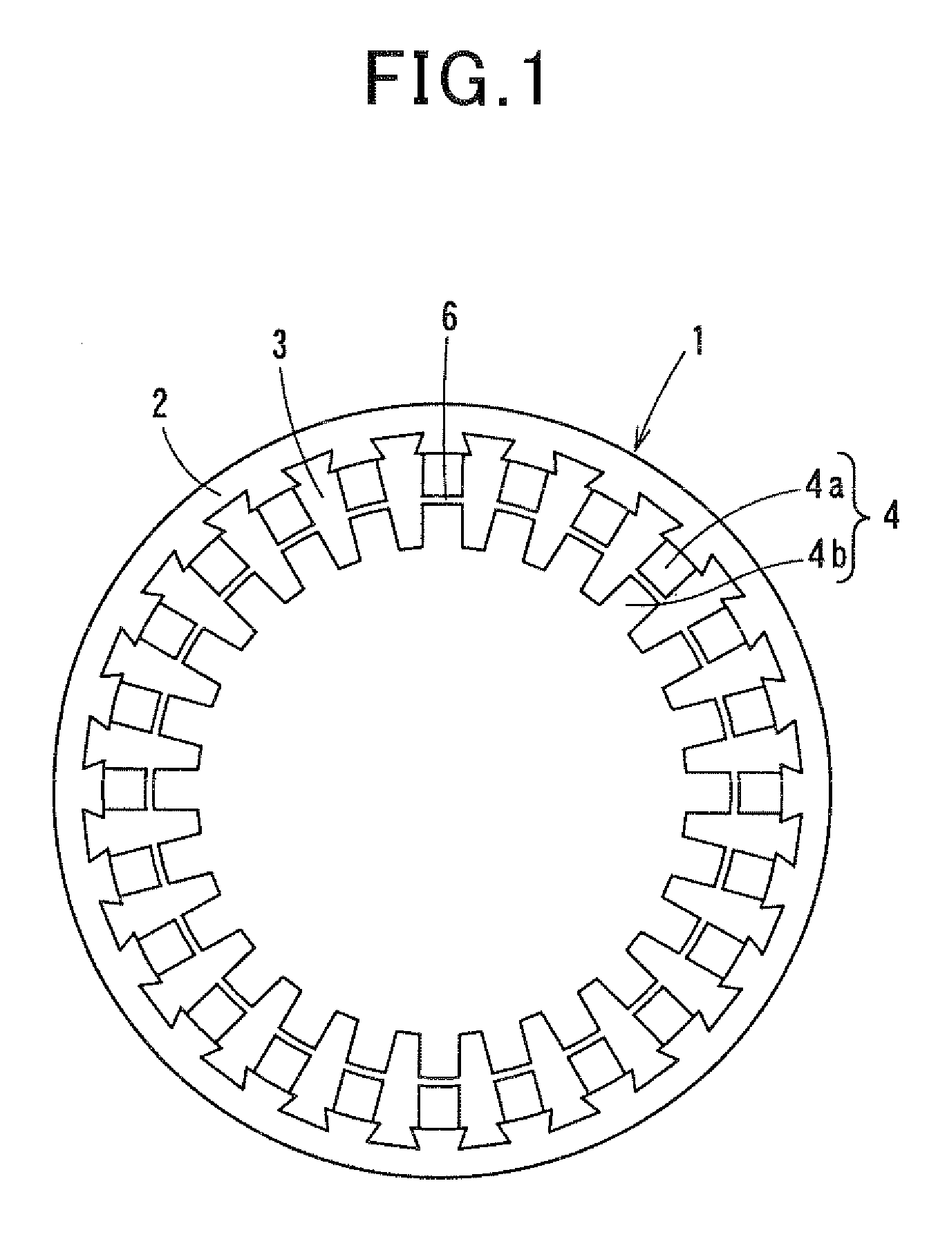
[0035]FIG. 1 shows the overall configuration of a stator core 1 of a stator according to the first embodiment of the invention. The stator is for use in an AC motor, such as an induction motor or a synchronous motor. More particularly, in the present embodiment, the stator is configured to be used in an 8-pole, 24-slot, 3-phase, full-pitch and distributed winding motor.
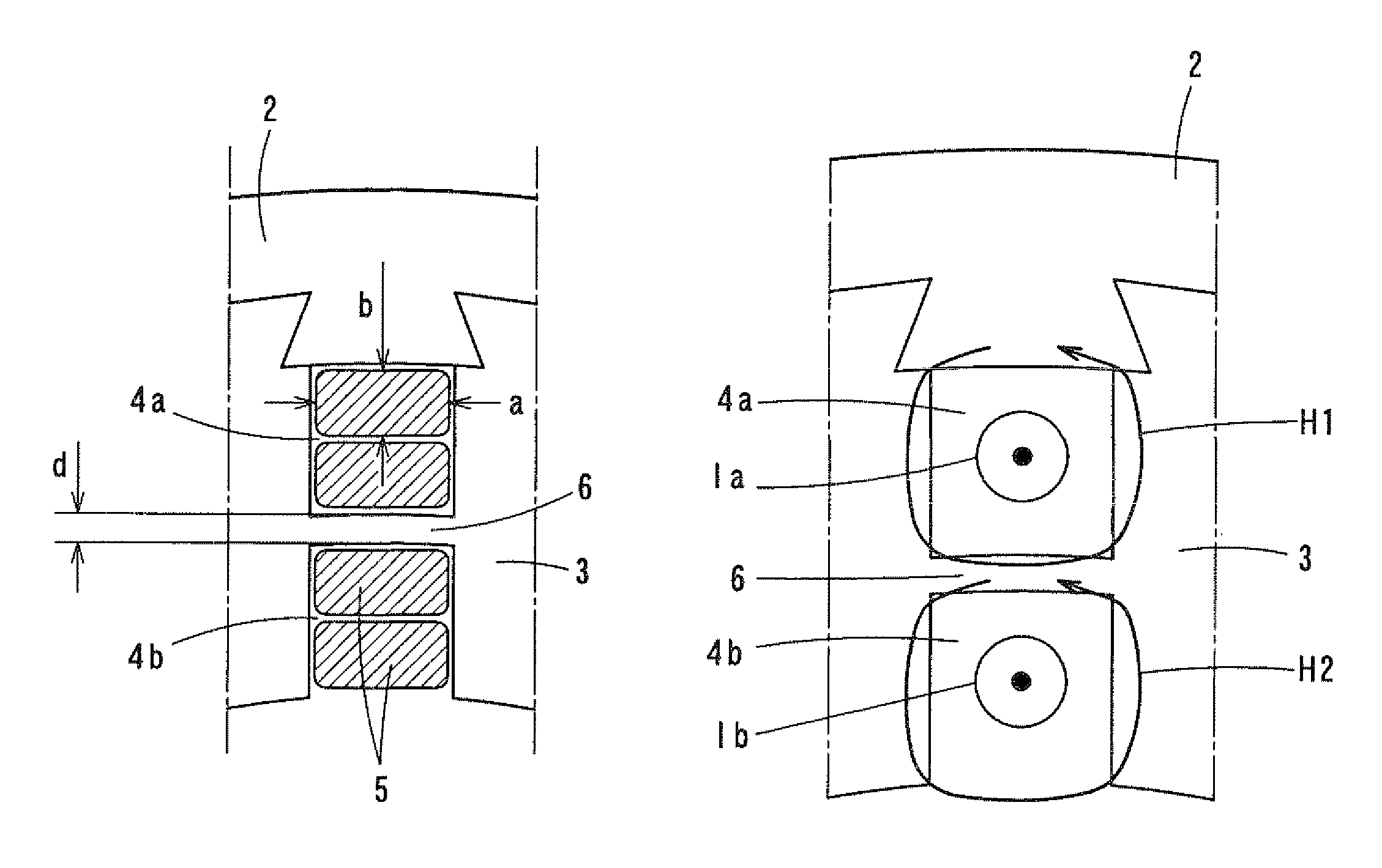
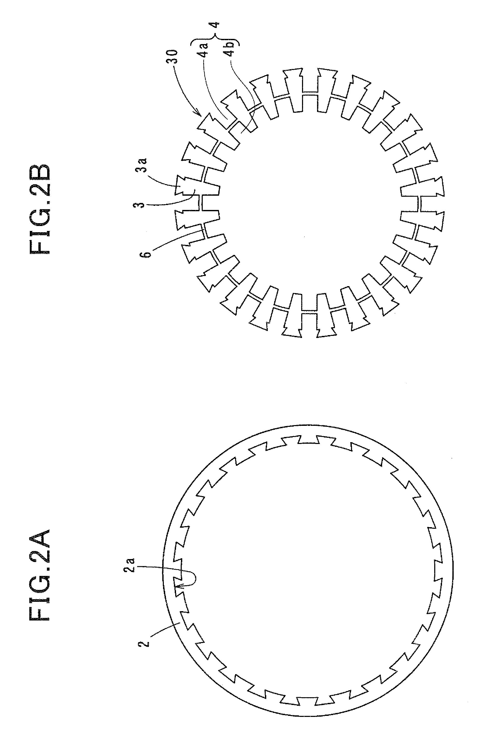
[0036]As shown in FIG. 1, the stator core 1 includes an annular yoke portion 2, a plurality of tooth portions 3 and a plurality of slots 4. Each of the tooth portions 3 extends radially inward from a radially inner periphery of the yoke portion 2. The tooth portions 3 are arranged at predetermined intervals in the circumferential direction of the annular yoke portion 2. Each of the slots 4 is formed between a circumferentially-adjacent pair of the tooth portions 3. In addition, in the present embodiment, both the number of the tooth portions 3 and the number of the slots 4 are set to be equal to 24.
[0037]The stator fu...
second embodiment
[0070]In the previous embodiment, the circumferential width of each of the tooth portions 3 of the stator core 1 is gradually decreased in the radially inward direction, thereby making the circumferential width of each of the slots 4 formed between the tooth portions 3 constant in the radial direction.
[0071]In comparison, referring to FIG. 7, in this embodiment, the circumferential width of each of the tooth portions 3 of the stator core 1 is set to be constant in the radial direction. Consequently, the circumferential width of each of the slots 4 formed between the tooth portions 3 is gradually decreased in the radially inward direction.
[0072]Setting the circumferential width of each of the tooth portions 3 as above, it is possible to keep the cross-sectional area of a magnetic path formed by the tooth portion 3 constant in the radial direction. As a result, it is possible to prevent each of the tooth portions 3 from being magnetically saturated.
[0073]Moreover, referring to FIG. 8,...
third embodiment
[0074]In the first embodiment, for each of the recesses 2a of the yoke portion 2 of the stator core 1, the circumferential width of the recess 2a is gradually increased in the radially outward direction. Moreover, the protrusions 3a of the tooth portions 3 are so shaped that each of the protrusions 3a can be fitted into a corresponding one of the recesses 2a of the yoke portion 2 with almost no clearance therebetween. Consequently, when viewed along the axial direction of the yoke portion 2, the recesses 2a of the yoke portion 2 and the protrusions 3a of the tooth portions 3 each have a trapezoidal shape tapering radially inward (see FIGS. 2A-2B).
[0075]In comparison, referring to FIG. 9, in this embodiment, for each of the recesses 2a of the yoke portion 2, the circumferential width of the recess 2a is set to be constant in the radial direction. Moreover, the protrusions 3a of the tooth portions 3 are so shaped that each of the protrusions 3a can be fitted into a corresponding one o...
PUM
 Abstract
Description
Claims
Application Information
 - R&D
- Intellectual Property
- Life Sciences
- Materials
- Tech Scout
- Unparalleled Data Quality
- Higher Quality Content
- 60% Fewer Hallucinations
Browse by: Latest US Patents, China's latest patents, Technical Efficacy Thesaurus, Application Domain, Technology Topic, Popular Technical Reports.
© 2025 PatSnap. All rights reserved.Legal|Privacy policy|Modern Slavery Act Transparency Statement|Sitemap|About US| Contact US: help@patsnap.com


