Electric power steering apparatus and electric motor driving controller used for the apparatus

a technology of electric motors and steering apparatuses, which is applied in the direction of motor control of motor oscillation damping, non-deflectable wheel steering, underwater vessels, etc., can solve the problems of electric motor ripple, worse steering feeling, and damage to vehicle salability, and achieve constant torque of electric motors.

Inactive Publication Date: 2011-09-22
HONDA MOTOR CO LTD
View PDF7 Cites 27 Cited by
  • Summary
  • Abstract
  • Description
  • Claims
  • Application Information

AI Technical Summary

Benefits of technology

[0011]According to this constitution, when the voltage saturation defined by the ratio of the driving voltage of the electric motor to the power supply voltage is high, the rotational speed is increased by supplying the large field weakening current. Also, when the voltage saturation is low, the rotational speed is decreased by decreasing the field weakening current. On the other hand, because the driving voltage can be decreased by increase in the rotational speed, a feedback control is performed so that the voltage saturation is decreased. Therefore, because there is room for the driving voltage of the electric motor, the predetermined torque can be kept by a constant torque current while suppressing the torque ripple of the electric motor. That is, the torque ripple of the electric motor caused by the voltage saturation of the driving voltage can be suppressed while keeping the torque of the electric motor constant. For this reason, the electric power steering apparatus can achieve the light steering feeling.
[0013]Also, the nearer to an upper limit the voltage saturation calculated by the voltage saturation calculating unit is, the larger absolute value of the field weakening current the field weakening current setting unit sets. According to this constitution, the nearer to the upper limit the voltage saturation is, the larger the field weakening current is set. Therefore, when the voltage saturation becomes approximately 100%, the voltage saturation can be decreased so that there is room for the driving voltage while keeping the torque constant. As a result, because the large torque ripple does not occur in the electric motor, the light steering feeling can be kept at any time.
[0015]According to this constitution, because the field weakening current is set based on the voltage saturation of the electric motor, the torque ripple of the electric motor caused by the voltage saturation of the driving voltage can be suppressed while keeping the torque of the electric motor constant. For this reason, the electric motor controller of the electric power steering apparatus can achieve the light steering feeling.

Problems solved by technology

As a result, an unusual noise occurs in the electric motor, a steering feeling becomes worse, and salability as a vehicle is damaged.
However, because the current command limit value of the electric motor is corrected based on the voltage saturation (the duty ratio) of the driving voltage in the technique disclosed in JP 2008-079387 A, the torque ripple of the electric motor is suppressed, but the driving current of the electric motor is limited in a saturated state of the driving voltage.
For this reason, in the technique disclosed in JP 200D-079387 A, the reduction in the driving current makes the torque of the electric motor to be limited, and a steering operation of the electric power steering apparatus becomes heavy.
As a result, a steering feeling can not be obtained in the electric power steering apparatus.
On the other hand, in the technique disclosed in JP 2004-040883 A, when the power supply voltage (e.g., the battery voltage) is decreased and there is no room for reduction in the driving voltage of the electric motor (i.e., the driving voltage saturation is increased), a distortion may occur in a torque current of the electric motor.
That is, in the technique disclosed in JP 2004-040883 A, the torque ripple occurs in the electric motor, and good steering feeling may not be obtained.

Method used


Image

  • Electric power steering apparatus and electric motor driving controller used for the apparatus
  • Electric power steering apparatus and electric motor driving controller used for the apparatus
  • Electric power steering apparatus and electric motor driving controller used for the apparatus

Examples


Embodiment Construction

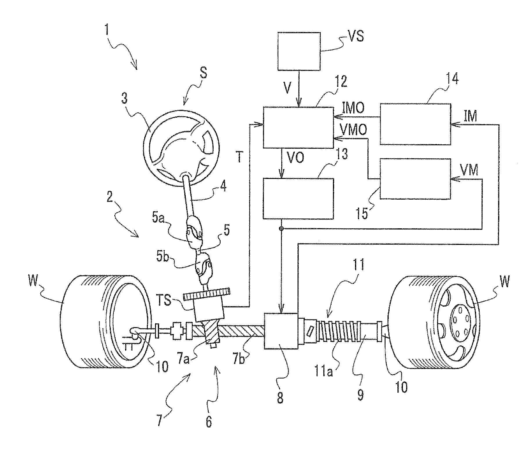
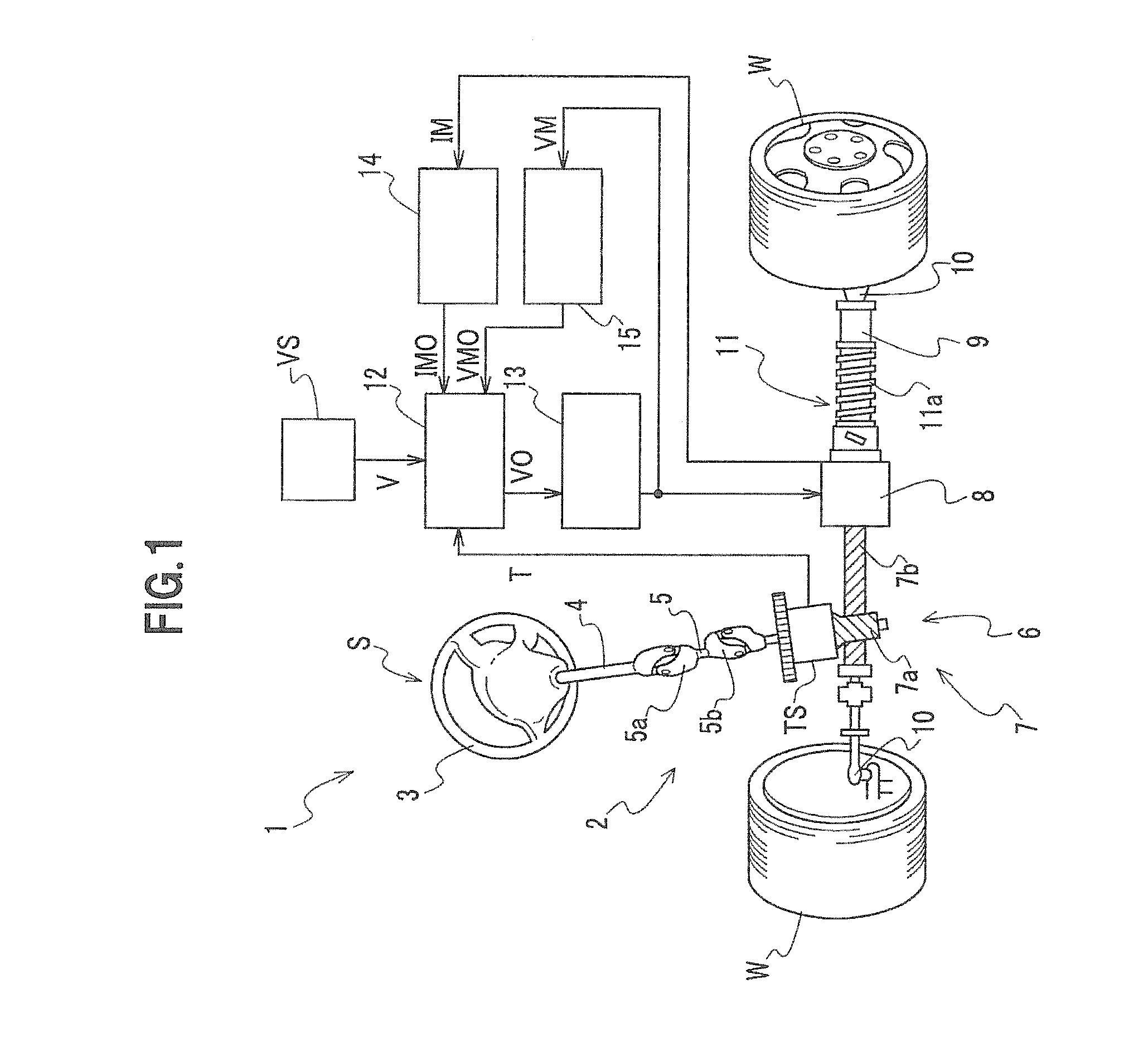
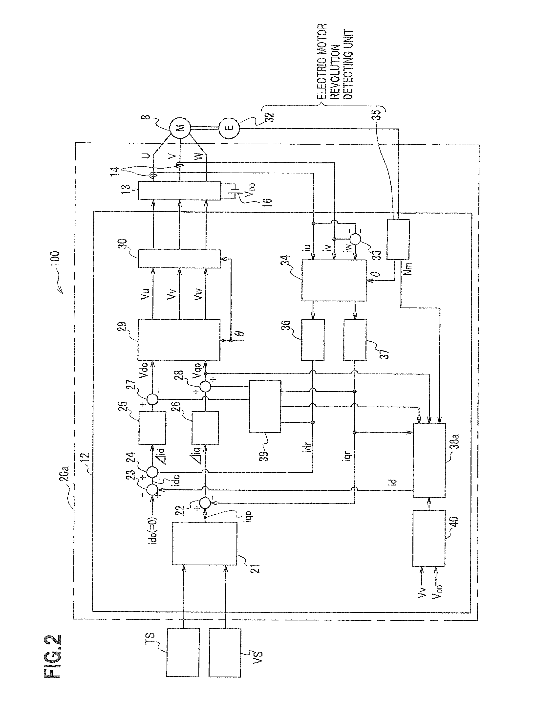
[0028]The present invention relates to an electric motor control of the electric power steering apparatus using a rotating magnetic field type electric motor (e.g., SPM (Surface Permanent Magnet) motor), and a field weakening control to weaken a field of the electric motor is performed based on a voltage saturation (or a duty ratio of ON time to 1 cycle time of a PWM control waveform) defined by a ratio of a driving voltage of the electric motor to a power supply voltage. For this reason, because a distortion in the driving current of the electric motor can be decreased by decreasing the voltage saturation (or the duty ratio), a torque ripple can be suppressed. Also, because a field weakening control is performed using the SPM motor, a predetermined torque current can be supplied to the electric motor, and the torque can be kept. Therefore, if the voltage saturation becomes high, the electric power steering apparatus can keep a stable steering assistance by performing such an electr...


PUM


Abstract

A q-axis target current setting unit generates a q-axis current command value based on a steering input signal from a steering torque sensor and a vehicle speed signal from a vehicle speed sensor. An electric motor generates a predetermined torque based on the q-axis current command value and a q-axis current (a torque current) to which a fed back q-axis real current is added. On the other hand, a d-axis correction current setting unit sets a field weakening current (a d-axis current) in response to a voltage saturation (duty ratio=driving voltage of electric motor / power supply voltage) output from a voltage saturation calculating unit. For this reason, when the voltage saturation becomes high, distortion (harmonics component) in current can be decreased by decreasing the voltage saturation while keeping the torque constant using a predetermined torque current, and a torque ripple can be suppressed.

Description

CROSS-REFERENCE TO RELATED APPLICATION[0001]The present application claims benefit of priority under 35 USC 119 to Japanese Patent Application No. 2010-060751 filed on May 17, 2010 the entire contents of which are hereby incorporated by reference.BACKGROUND OF THE INVENTION[0002]1. Field of the Invention[0003]The present invention relates to an electric power steering apparatus and an electric motor driving controller used for the apparatus, and more particularly, to an electric power steering apparatus for assisting a steering effort of a vehicle by power of the electric motor and the electric motor driving controller used for the apparatus.[0004]2. Description of the Related Art[0005]Conventionally, a permanent magnet type brushless DC motor has been preferably used as an electric motor used for an electric power steering apparatus mounted on a vehicle such as an automobile, etc. In such an electric motor (hereinafter, merely referred to as a motor), when a driving voltage of the ...

Claims


Application Information

Patent Timeline
Patent Type & Authority Applications(United States)
IPC IPC(8): B62D6/00B62D5/04B62D119/00H02P6/06H02P6/08H02P6/17H02P6/28H02P21/00H02P21/05H02P21/22H02P23/04H02P27/04H02P27/08
CPCB62D5/046H02P21/06B62D5/0463
Inventor OHNO, SATOSHIMIYOSHI, TAKASHIYONEDA, ATSUHIKOSHIMIZU, YASUO
Owner HONDA MOTOR CO LTD
Why Eureka
Try Eureka